E-34
English
12
12 Extended Installation Instructions for the Heat Pump Manager
(Heating/Cooling)
12.1 Heating and Cooling Controller
The system supports two modes for generating the
refrigerating capacity:
Active cooling with a reversible heat pump
Passive cooling using a heat exchanger
In order to perform cooling functions, a cooling controller is
required in addition to the heat pump controller (heating).
Reversible heat pumps for active cooling are supplied as
standard with a heat pump manager (heating/cooling)
For passive cooling, the cooling controller is connected to
the existing heat pump manager (heating).
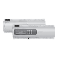
Fig. 12.1: Dimensions of the wall-mounted heat pump manager
heating/cooling
12.1.1 Network Operation of Heating and Cooling Controllers and Remote Control
Both of the controllers (heating and cooling controllers) are
connected to the J11 plugs via a three-core connecting cable and
are operated as a network. This is done by assigning each
controller a network address. The network addresses of the
heating and cooling controllers are preassigned.
These controller addresses are factory default settings.
Exception: Heating controller for passive cooling station. See the
Passive Cooling Station installation instructions.
The heating and cooling controller software must be compatible
in order for the network to work properly.
The software is compatible if the characters X and Y are
identical, e.g.
WPM_ K_H41 is compatible with WPM_H_H45
WPM_ K_H41 is not compatible with WPM_H_H31
Use the “Operating data network” menu to check if the cooling
controller was identified.
The “Network heating/cooling” menu point displays whether
the network connection is active.
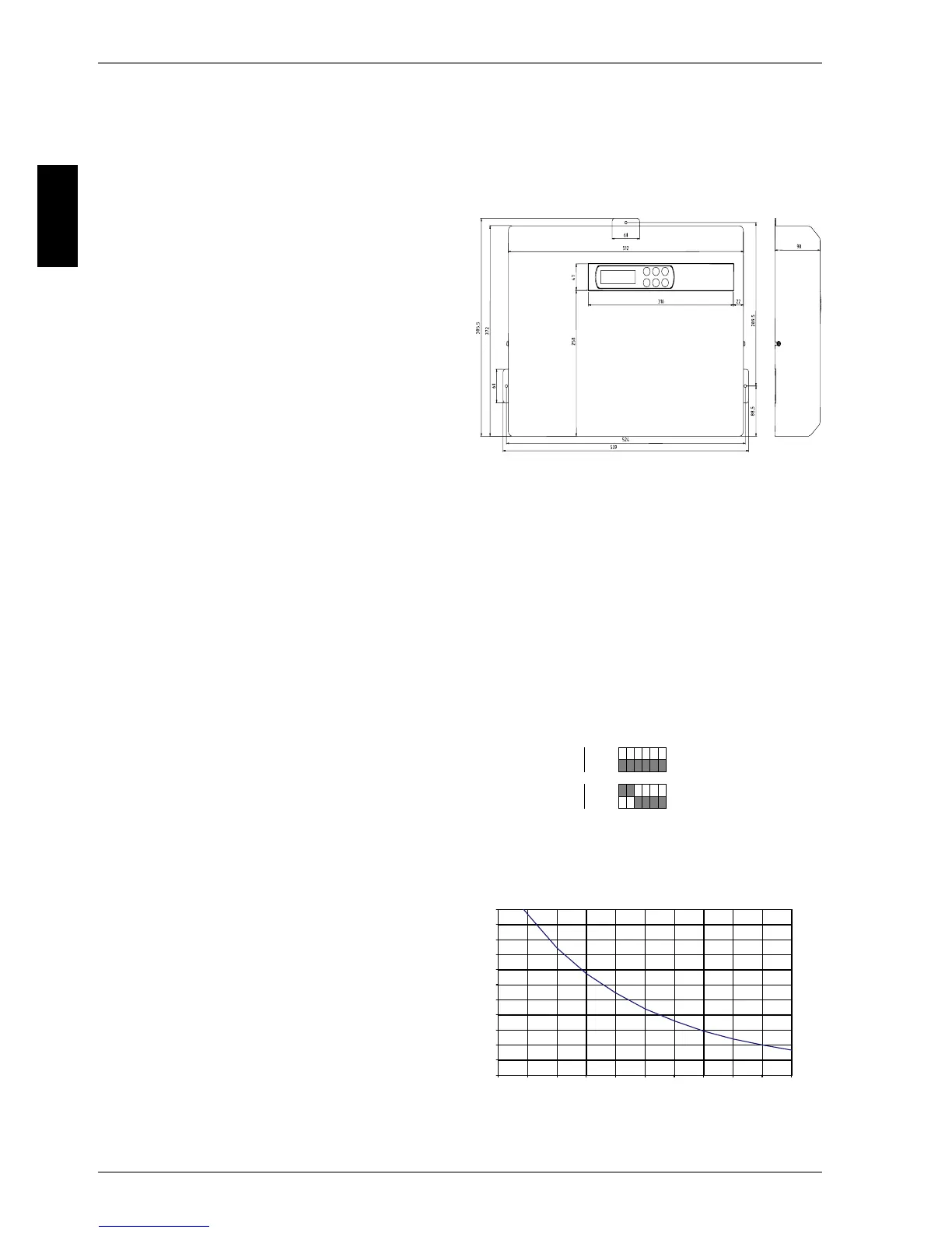
Set the DIP switches of a connected remote control as follows:
Fig. 12.2: DIP switch settings
12.1.2 Temperature Sensor (Cooling Controller)
All temperature sensors to be connected to the supplementary
cooling controllers have the illustrated sensor characteristic
curve.
Room temperature sensor for room climate control station
Flow sensor for passive cooling
Return flow sensor for passive cooling
Fig. 12.3: NTC sensor for cooling controller
Heating controller Network address 01
Cooling controller Network address 02
Heating software WPM_H_ X Y Z
Cooling software WPM_K_ X Y Z
Remote control
No network
Network
123456
7HPSHUDWXUHLQ
>
&@
5HVLVWDQFHYDOXHLQ
>N2KP@
 Loading...

