6
© 2015 Directed. All rights reserved.
Wiring Connections
Main Harness, White 5-pin connector
1
BLACK (-) CHASSIS GROUND
2 BROWN (+) SIREN OUTPUT
3 RED (+) FUSED 12V DC CONSTANT INPUT
4 ORANGE (-) 500mA GWA (GROUND WHEN ARMED) OUTPUT
5 WHITE (+)/(-) SELECTABLE PARKING LIGHT OUTPUT (FUSED)
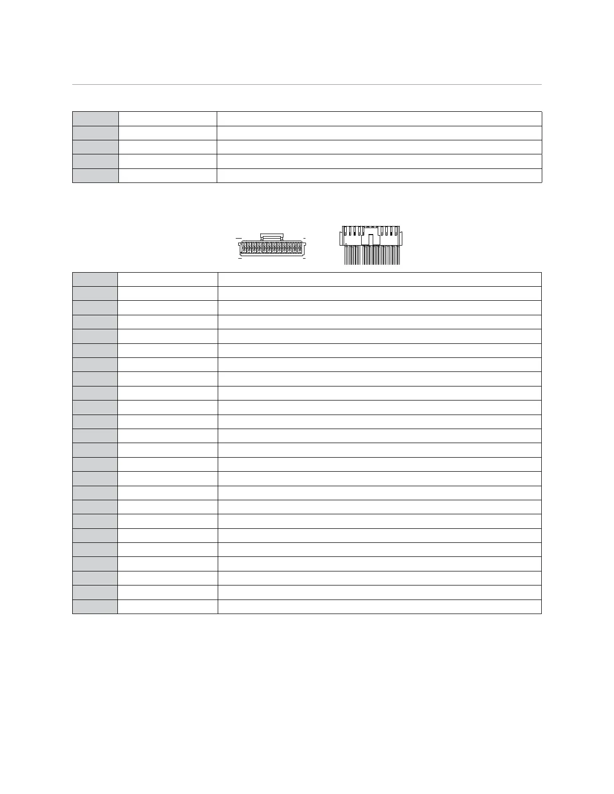
Auxiliary/Shutdown/Trigger Harness, White 24-pin connector
1 3 5
WIRE SIDE
2 4 6 24
23PINK/WHITE VIOLET/WHITE
GREEN/WHITEBLACK/WHITE
1 2 3
WIRE SIDE
13 24
12PINK/WHITE VIOLET/WHITE
GREEN/WHITEBLACK/WHITE
1 PNK/WHITE (-) 200mA IGNITION 2/ACCESSORY OUTPUT
2 BLUE/WHITE (-) 200mA 2ND STATUS /REAR DEFOGGER OUTPUT
3 RED/WHITE (-) 200mA TRUNK RELEASE OUTPUT
4 BLACK/YELLOW (-) 200mA DOME LIGHT OUTPUT
5 DARK BLUE (-) 200mA STATUS OUTPUT
6 WHITE/BLACK (-) 200mA AUX 5 OUTPUT
7 WHITE/VIOLET (-) 200mA 2nd UNLOCK OUTPUT
8 ORANGE/BLACK (-) 200mA AUX 6 OUTPUT
9 GRAY (-) HOOD PIN INPUT
10 BLUE (-) TRUNK PIN/INSTANT TRIGGER INPUT
11 WHITE/BLUE ** (-) REMOTE START ACTIVATION INPUT
12 VIOLET/WHITE TACHOMETER INPUT
13 BLACK/WHITE* (-) PARKING BRAKE INPUT/EMERGENCY INPUT
14 GREEN/BLACK (-) 200mA FACTORY ALARM DISARM OUTPUT
15 GREEN (-) DOOR INPUT
16 BROWN/BLACK (-) 200mA HORN HONK OUTPUT
17 PINK (-) 200mA IGNITION 1 OUTPUT
18 VIOLET (+) DOOR INPUT
19 VIOLET/BLACK (-) 200mA AUX 4 OUTPUT
20 BROWN (+) BRAKE SHUTDOWN INPUT
21 VIOLET/YELLOW (-) 200mA STARTER OUTPUT
22 GRAY/BLACK (-) DIESEL WTS (WAIT-TO-START) INPUT
23 ORANGE (-) 200mA ACCESSORY OUTPUT
24 GREEN/WHITE (-) 200mA FACTORY ALARM ARM OUTPUT
* Connect this wire to one of the wires on the provided Remote Start Shutoff Switch. The other wire on
the switch connects to the (-) Parking Brake/Emergency Brake wire in the vehicle. The switch must be in
the ON position for the remote start to work.
** This wire not only activates the remote start, it can also be used to change feature options when pro-
gramming. See Programming System Features.
Important: NEVER connect 200mA low current outputs directly to a motor or high current device WITHOUT
a relay.