34
IP2246EN
EN
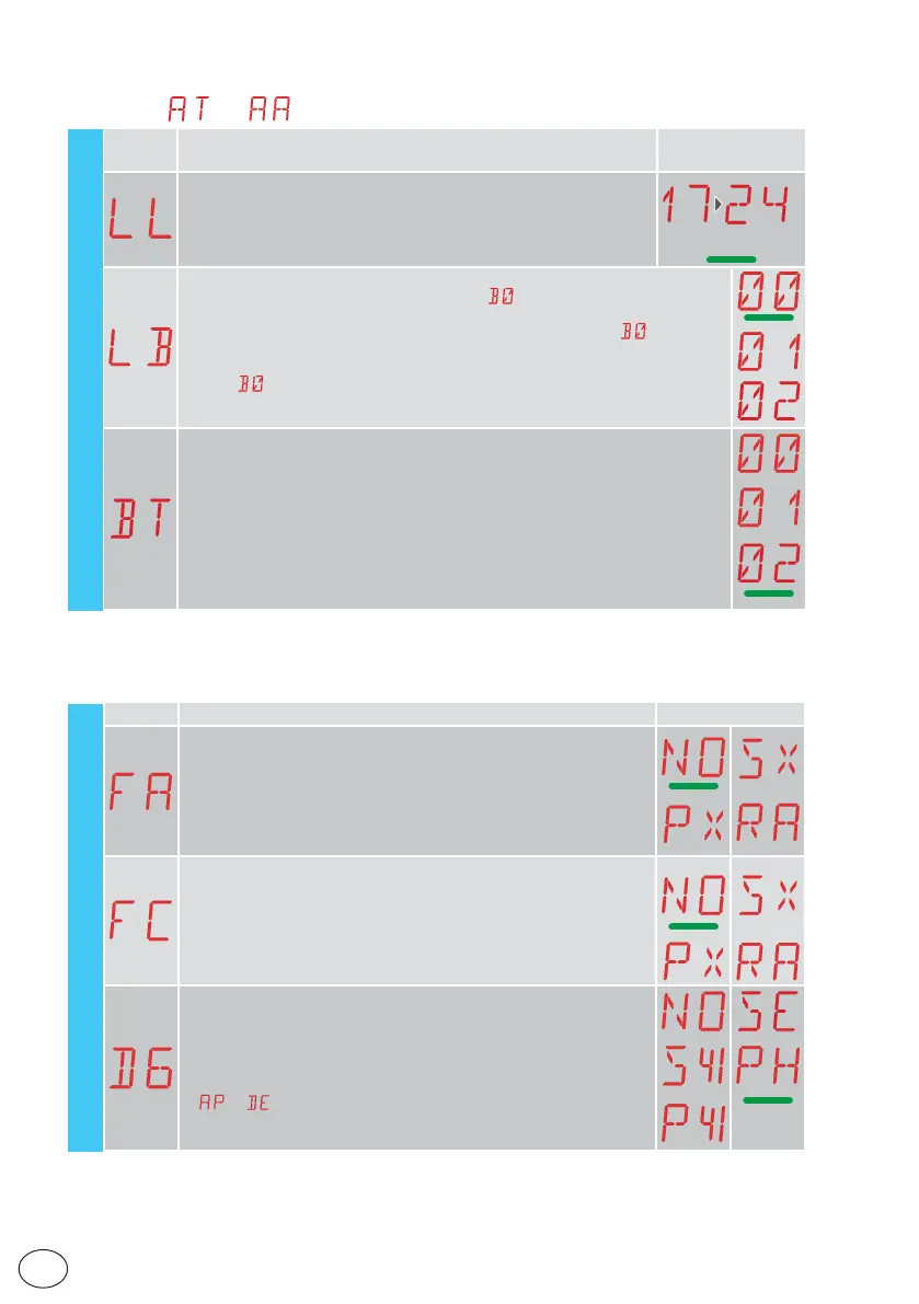
11.8.1 Additional EM level parameters that can be configured (available
with
→ enabled)
Display Description
Selections
available
LL - Voltage threshold for indicating that batteries are almost flat (V)
17 - Minimum
24 - Maximum
NOTE: it is set with an interval of sensitivity of 0.5V shown when the
decimal point on the right lights up.
22
LB - Indication that batteries are almost flat
00 - Visualisation on display (alarm message
)
01 - Visualisation on flashing light (with the automation idle, 2 flashes are made
and then repeated every hour) and on display (alarm message
)
02 - Visualisation on "open gate" indicator light (with the automation closed, 2
flashes are made and then repeated every hour) and on display (alarm mes-
sage
)
BT - Battery mode
00 - Anti-panic (performs the opening operation following a mains supply fail-
ure. The automation opens but does not accept any other commands until the
mains supply has been restored).
01 - Continuous operation - the last operation performed before control panel
switch-off will be an opening.
02 - Continuous operation - the last operation performed before control panel
switch-off will be an closure.
11.9 Second level menu - AP (Advanced Parameters)
Display Description Selections available
FA - Selection of opening limit switch mode
NO - None
SX - Stop limit switch (after activation, the gate wing stops its movement)
PX - Proximity limit switch (after activation, the gate wing continues as
far as the end stop and any obstacle is considered a stop)
RA - Deceleration limit switch (after activation, the gate wing slows
down its movement)
FC - Selection of closing limit switch mode
NO - None
SX - Stop limit switch (after activation, the gate wing stops its movement)
PX - Proximity limit switch (after activation, the gate wing continues as
far as the end stop and any obstacle is considered a stop)
RA - Deceleration limit switch (after activation, the gate wing slows
down its movement)
D6 - Selection of device connected to terminals 1-6
NO - None
SE - Safety edge (if contact 1-6 opens, there is a disengagement of
10cm after the stop)
S41 - Safety edge with safety test (if contact 1-6 opens, after the stop
there is a disengagement of a duration depending on the selection
→ )
PH - Photocells
P41 - Photocells with safety test
AP - Advanced parameters EM - Energy management