18
IP2246EN
EN
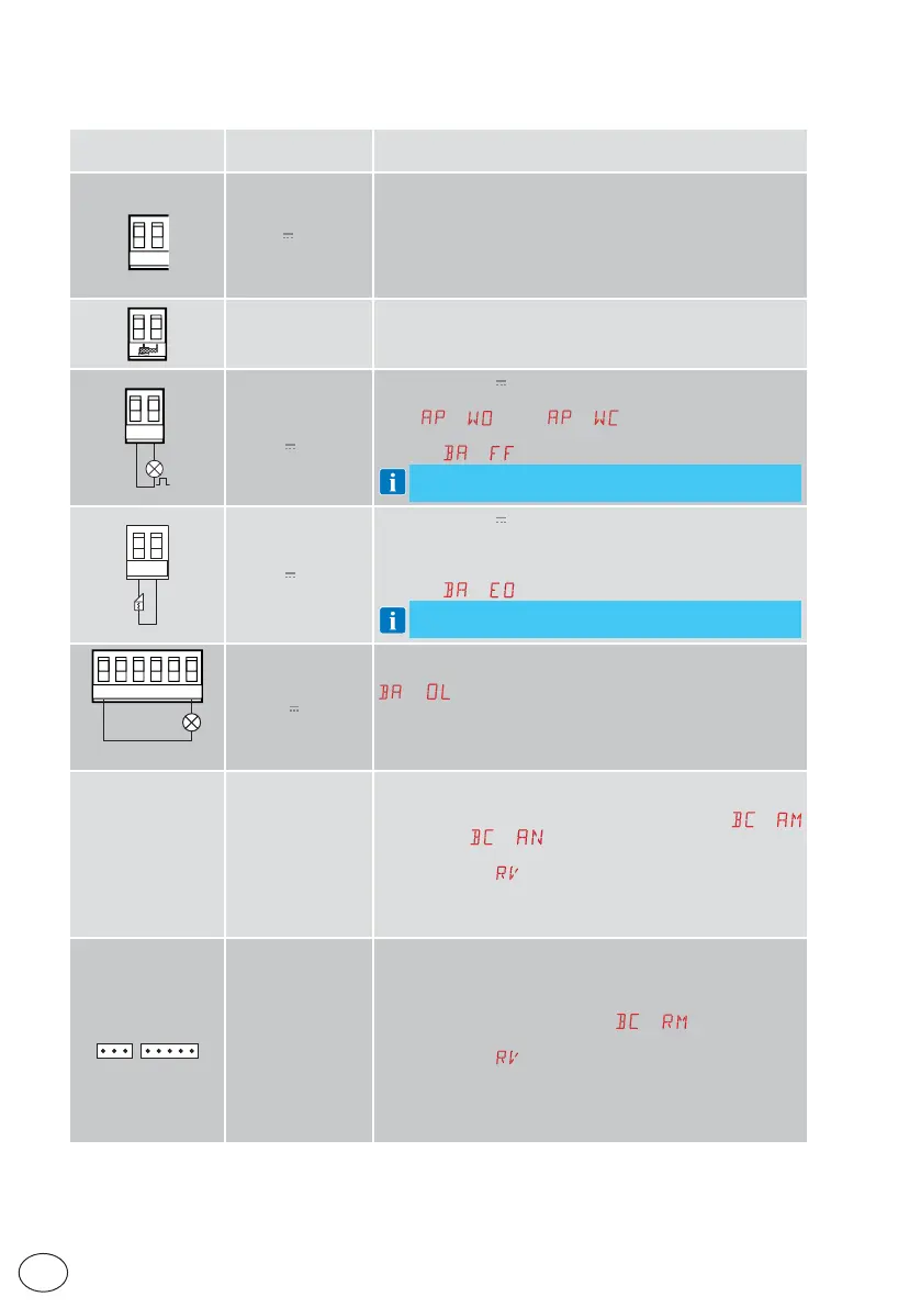
9. Outputs and accessories
Output
Value of
accessories
Description
0
-
1
+
24V / 0.5 A
Power supply to accessories
Output for power supply to external accessories.
NOTE: the maximum absorption of 0.5A corresponds to the
sum of all terminals 1.
The "gate open" indicator light (30-13) is not calculated in the
0.5A indicated above. The maximum value to be considered is 3W.
GOL148REA
If the GOL868R4 radio receiver is used (868.35 MHz), connect the
supplied antenna wire (90mm).
+LP-
FL24
24V
/ 25W
Configurable 24V
output (default: flashing)
The pre-flashing settings can be selected from the third level
menu
→ and/or → .
To modify the operating mode of the LP output, refer to the
selection
→ .
NOTE: compatible with 12/24 V~ electric locks
-+LK
24V / 15W
Configurable 24V output (default: electric lock)
It is activated when the operation begins with the automation
closed.
To modify the operating mode of the LK output, refer to the
selection
→ .
NOTE: compatible with 12/24 V~ electric locks
30 2 3 4 9 13
24V / 3W
Automation status lamp
For the operating mode of output 30-13, refer to the selection
→ .
AUX 1
AUX 2
BIXR2
BIXPR2
LAB9
LAN7S
MOBCRE
SOFA1 – SOFA2
GOPAVRS
The control panel has two slots for plug-in command and
safety boards.
The action of the control board can be selected using
→
for AUX1 and
→ for AUX2.
When using slot-in radio boards, remove the RDX module. The
display will show
.
WARNING: the plug-in board must be inserted and removed
with the power supply disconnected.
WARNING: BIXLR42 not compatible with AUX slot
RDX
ZENRS
ZENPRS
The control panel is fitted with a housing for modules of the
ZENRS radio receiver type (433.92MHz).
Can be replaced with a radio receiver module of the ZENPRS
type (868.35MHz).
The operating mode is selected via
→ .
When using slot-in radio boards, remove the RDX module. The
display will show
.
Warning: the modules must be inserted and removed with the
power supply disconnected.