XT30/XT50 Installation Guide Digital Monitoring Products
5
INSTALLATION
Installation
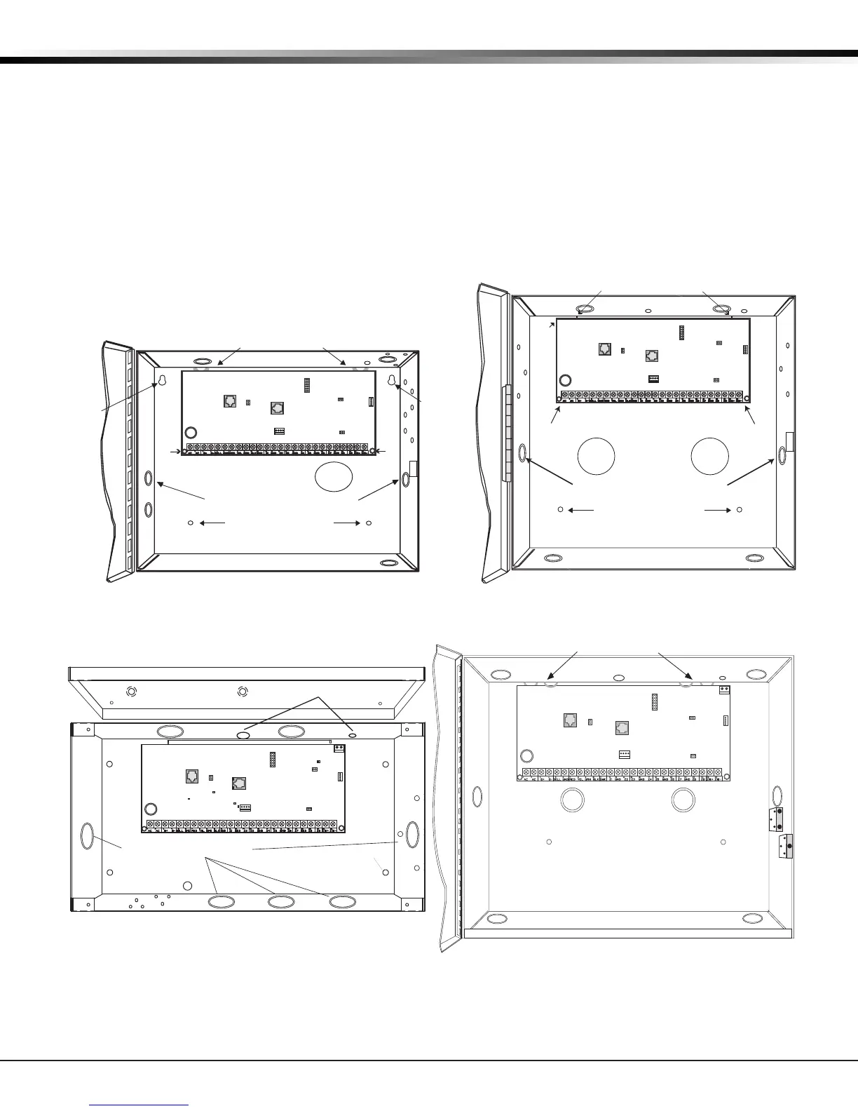
4.1 Mounting the Enclosure
The metal enclosure must be mounted in a secure, dry place to protect the panel from damage due to
tampering or the elements. It is not necessary to remove the PCB when installing the enclosure. The PCB
may be installed in the standard 340 Small enclosure, optional 341 Kiosk enclosure, optional 349 Medium
enclosure, or the optional 349A Attack enclosure.
When using cellular communication or on-board wireless with the 341 enclosure, an SMA and wireless
antenna exit may be added at the time of the installation. The 349A Attack Resistant enclosure is factory
shipped with one knockout on the top left of the enclosure. As needed, additional knockouts may be added
at the time of installation. See Figure 3 for the positions on the enclosure that can be added. Each
additional knockout must be lled with conduit.
Dual 1/2" and 3/4" Conduit Knockout
Battery Shel
f
Enclosure Mounting Hole
s
Slide panel PCB into lower enclosure slots
Panel
PCB
screw
Model 349INT Enclosure
Slide panel PCB between formed metal supports
Dual 1/2" and 3/4" Conduit Knockouts
Battery Shelf
Enclosure Mounting Holes
Enclosure
Mounting
Hole
Enclosure
Hole
Panel
PCB
screw
Model 340INT Enclosure
J3
Phone
Line
Outputs
J11
1
2
3
4
J1
Ethernet
J16
Reset
J7 RJ
Supervision
J24
Celllular
header
connection
Panel
PCB
screw
Panel
PCB
screw
Enclosure
Mounting
Hole
J3
Phone
Line
Outputs
J11
J1
Ethernet
J16
Reset
J7 RJ
Supervision
J24
Celllular
header
connection
1
2
3
4
J18
Load
RED
Programming
J8
J18
Load
RED
Programming
J8
Figure 2: Standard 340 Enclosure (left), Optional 349 Enclosure (right)
Figure 3: Optional 341 Enclosure (left), Optional 349A Enclosure (right)
3-Hole
Pattern for
Accessory
Modules
* 349A Optional Knockout
Front and
Rear Tamper
Switches for
350A Attack
Resistant
Enclosure
Dual 1 3/4" and 1 3/8" Conduit Knockouts
Battery Shelf
*
*
*
*
*
Model 349A Enclosure
Slide panel PCB between formed metal supports
J3
Phone
Line
Outputs
J11
1
2
3
4
J1
Ethernet
J16
Reset
J20
Wireless
Antenna
connection
J7 RJ
Supervision
J24
Celllular
header
connection
J18
Load
RED
Programming
J8
Lid Mounting Holes (4 places)
Lid Mounting Holes
(4 places)
Enclosure Mounting Holes (4 places)
PEMs for optional battery bracket
Dual 1/2" and 3/4" Conduit Knockouts
J3
Phone Line
Outputs
J11
1
2
3
4
J1
Ethernet
J16
Reset
J20
Wireless
Antenna
connection
(XT50 only)
J7 RJ
Supervision
J24 Celllular
header
connection
J18
Load
Programming
J8
OVC LED
Power
LED
XMIT
TX RX
Wireless LEDs
RCV
Tamper Mounting Holes
(Upper and Lower)
Openings drilled
at installation
Model 341 Enclosure