Digital Monitoring Products XT30/XT50 Installation Guide
10
INSTALLATION
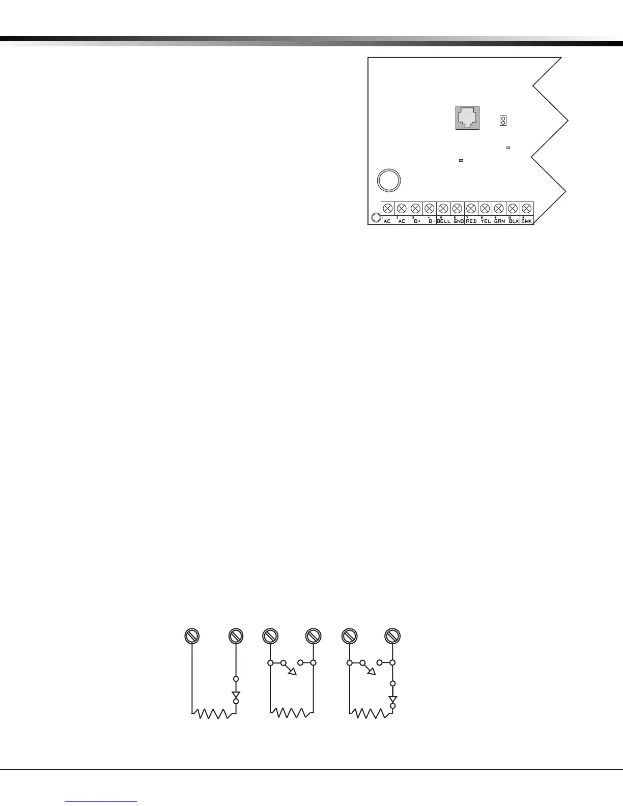
8.9 Overcurrent OVC LED
The Overcurrent LED (OVC) lights Red when the devices
connected to the Keypad Bus draw more current than the
auxiliary output rating. The OVC LED is located above
terminals 9 and 10 as shown in Figure 5. When the OVC LED
lights Red, the Keypad bus/auxiliary power (terminal 7) and
the PROG header shut down.
Smoke and Glassbreak Detector Output
9.1 Terminal 11
Nominal 12VDC at 100mA maximum (shared by terminal 25) is
supplied at terminal 11 to power 4-wire smoke detectors or
other auxiliary powered devices. This output can be turned
o by the user for 5 seconds using the Sensor Reset option
in the User Menu. Terminal 10 is the ground reference for
terminal 11.
Burglary Zones
10.1 Description
On XT30/XT50 panels, terminals 12 to 24 are the nine burglary zones. For programming purposes, the zone
numbers are 1 to 9. The zone congurations on terminals 12 to 24 are described below.
Terminal Function Terminal Function
12 Zone 1 voltage sensing 19 Ground for zones 5 & 6
13 Ground for zones 1 & 2 20 Zone 6 voltage sensing
14 Zone 2 voltage sensing 21 Zone 7 voltage sensing
15 Zone 3 voltage sensing 22 Ground for zones 7, 8, & 9
16 Ground for zones 3 & 4 23 Zone 8 voltage sensing
17 Zone 4 voltage sensing 24 Zone 9 voltage sensing
18 Zone 5 voltage sensing
The voltage sensing terminal measures the voltage across the 1k Ohm End-of-Line resistor and the zone’s
ground terminal. Dry contact sensing devices can be used in series (normally-closed) or in parallel (normally-
open) with any of the burglary protection zones.
10.2 Operational Parameters
Each burglary protection zone detects three conditions: open, normal, and short.
The parameters for each are listed below:
Condition Resistance on zone Voltage on zone terminal
Open over 1300 ohms over 2.0VDC
Normal 600 to 1300 ohms 1.2 to 2.0VDC
Short under 600 ohms under 1.2VDC
J3
Phone Line
J7 RJ
Supervision
OVC LED
Power
LED
Figure 5: OVC LED location
1K Ohm
Normally
Closed
1K Ohm
Normally Open
1K Ohm
Combination Normally Open
and Normally Closed
Figure 6: Protection Zone Contact Wiring