XT30/XT50 Installation Guide Digital Monitoring Products
7
INSTALLATION
Secondary Power Supply
6.1 Battery Terminals 3 and 4
Connect the black battery lead to the
negative battery terminal. The negative
terminal connects to the enclosure ground
internally through the XT30 or XT50 circuit
board. Connect the red battery lead to the
positive battery terminal. Observe polarity
when connecting the battery.
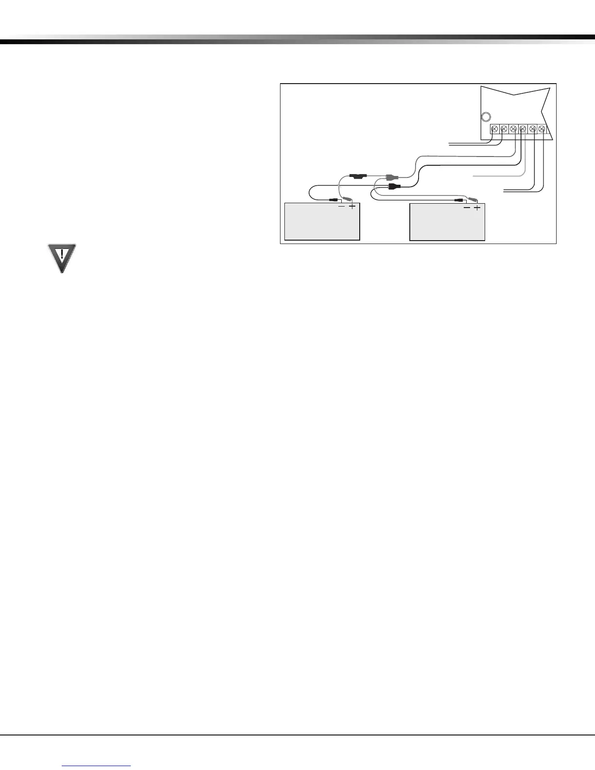
Add a second battery in parallel using the
DMP Model 318 Dual Battery Harness. DMP
requires each battery be separated by
a PTC in the battery harness wiring to
protect each battery from a reversal or
short within the circuit. See Figure 4.
Use sealed lead-acid batteries only:
Use 12VDC sealed lead-acid rechargeable
battery. Batteries supplied by DMP have been tested to ensure proper charging with DMP products.
GEL CELL BATTERIES CANNOT BE USED WITH THE XT30/XT50 PANEL.
6.2 Earth Ground
Terminal 4 of the panel must be connected to earth ground using 14 gauge or larger wire to provide proper
transient suppression. DMP recommends connecting to a metal cold water pipe or ground rod only. Do not
connect to electrical conduit or a telephone company ground.
6.3 Replacement Period
DMP recommends replacing the battery every 3 to 5 years under normal use.
6.4 Discharge/Recharge
The panel battery charging circuit oat charges at 13.9VDC at a maximum current of 1.2 Amps using a 40 VA
transformer. The total current available is reduced by the combined auxiliary current draw from terminals 7,
11, and 25. The various battery voltage levels are listed below:
Battery Trouble: Below 11.9VDC
Battery Restored: Above 12.6VDC
6.5 Battery Supervision
The panel tests the battery once every hour when AC power is present. This test occurs 15 minutes past
each hour and lasts for ve seconds. A load is placed on the battery and if its voltage falls below 11.9VDC a
low battery is detected. If AC power has failed, a low battery is detected any time the battery voltage falls
below 11.9VDC.
If a low battery is detected with AC power present, the test is repeated every two minutes until the battery
charges above 12VDC; the battery restored voltage. If a faulty battery is replaced with a fully charged
battery, the restored battery will not be detected until the next two-minute test is done.
6.6 XT30/XT50 Power Requirements
During AC power failure, the panel and all auxiliary devices connected draw their power from the battery.
All devices must be taken into consideration when calculating the battery standby capacity. On the following
page is a list of the power requirements of the panel. Add the additional current draw of DMP keypads,
smoke detector output, and any other auxiliary devices used in the system for the total current required.
The total is then multiplied by the total number of standby hours required to arrive at the total Ampere-
hours required.
AC
1 2 3 4
+BAC –B
318 Battery
Harness
Panel Red and
Black Battery Cables
Red
Black
Battery
Battery
Red
Black
5 6
BELL GND
To AC
14 AWG to
Earth Ground
XT30/XT50
Panel
PTC
To Bell
Circuit
Figure 4: Wiring Multiple Batteries