Digital Monitoring Products XT30/XT50 Installation Guide
12
INSTALLATION
PHONE LINE RJ Connector
13.1 Description
Connect the panel to the public telephone network by installing a DMP 356 RJ Cable between the panel’s
PHONE LINE connector and the RJ31X or RJ38X phone jack. CAUTION - To reduce the risk of re, use only No.
26 AWG or larger telecommunication line cord, such as DMP Model 356 Series Phone Cords.
A two pin RJ SUP header is provided to allow monitoring of the telephone cable connected between the
panel and a RJ38X jack (pins 2 and 7 jumpered). Attach a DMP Model 306 Harness between RJ SUP and any
available zone. The RJ SUP pins are connected via the telephone cable to the RJ38X jack pins 2 and 7. The
RJ38X jack provides a jumper between pins 2 and 7 which completes the circuit. Program the zone as a
Supervisory type (SV). When the telephone cable is removed, the keypad displays zone trouble and produces
a steady tone.
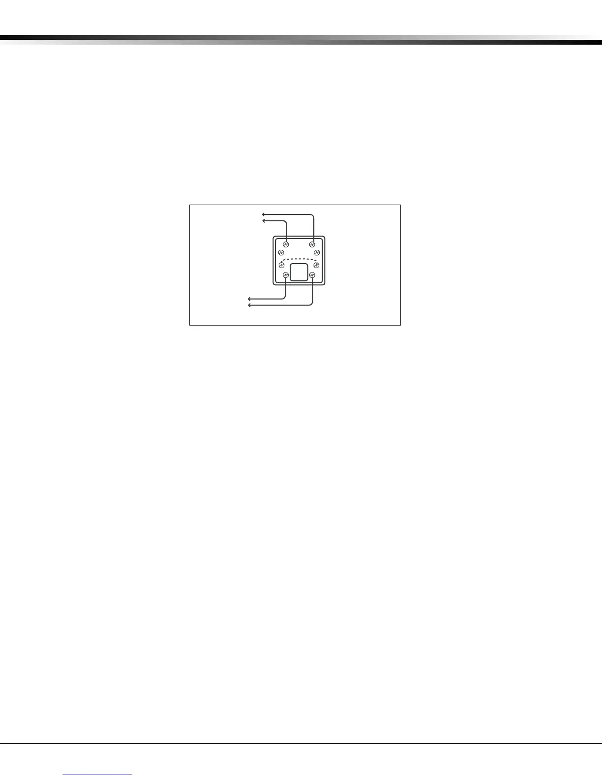
To Telephone
Line
RJ31X or RJ38X
Phone Block
8
7
6
54
3
2
1
Ring Tip
To Premise
Phone(s)
Ring 1
Tip 1
Figure 7: Phone Jack Wiring
13.2 FCC Registration
The panel complies with FCC part 68 and is registered with the FCC.
Registration number: CCKAL00BXT50
Ringer Equivalence: 0.0B
13.3 Notication
Registered terminal equipment must not be repaired by the user. In case of trouble, the device must be
immediately unplugged from the telephone jack. The factory warranty provides for repairs. Registered
terminal equipment may not be used on party lines or in connection with coin telephones. No tication must
be given to the telephone company with the following information:
a. The particular line(s) the service is connected to
b. The FCC registration number
c. The ringer equivalence
d. The make, model, and serial number of the device
ETHERNET Connector
14.1 Description
The ETHERNET Connector is available on the Network version and connects directly to an Ethernet network
using a standard patch cable.
14.2 Ethernet LEDs
The two LEDs, located on the left side of the ETHERNET Connector, indicate network operation. The top,
Link LED is a steady green light when an ethernet cable is connected. The bottom, Activity LED ashes
yellow to indicate messages are being received or transmitted.