XT30/XT50 Installation Guide Digital Monitoring Products
15
INSTALLATION
On-Board 1100 Series Wireless Antenna Connection
19.1 Wireless Antenna
The XT50 Wireless Antenna (ANT) terminal block is located at the top right corner of the circuit board. The
antenna installs through a small opening in the top of the enclosure and is attached to the panel using the
right terminal. The left terminal is not used.
The XT50 built-in wireless operates with DMP 1100 Series transmitters. See section 3.4 for a list of accessory
devices.
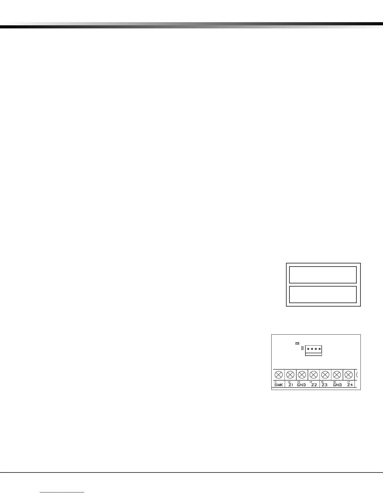
19.2 LED Operation
Green (TX): With a wireless house code enabled, the green LED ashes every time the receiver transmits
(32 times per second). If a house code is not programmed in the panel, the panel is reset, or the panel is
powered o, the green LED will be o. Under normal operation, the green LED ashes constantly with no
interruption or change.
Yellow (RX): The yellow LED ashes every time the receiver hears a message from a programmed wireless
transmitter. When a message is sent by a transmitter, typically by pressing or releasing the tamper switch,
the yellow LED should ash indicating that the receiver received a message from the transmitter. If the
LED never ashes, the transmitter is not getting through to the receiver. This could be because of a
misprogrammed serial number or the transmitter is too far away. Under normal operation, the yellow LED
will ash at every trip of every wireless transmitter and occasionally when the transmitters perform their
periodic check-in. It is not unusual for this LED to stay o for many minutes at a time when no transmitters
are communicating.
Wireless Keypads
20.1 Mounting Keypads
DMP keypads have removable covers that allow the base to be mounted on a wall, desk stand or other at
surface using the screw holes provided on each corner.
20.2 Wireless Keypad Association
Enable Wireless Keypad Association operation on both the keypad and panel.
To enable wireless keypad association operation on a LCD Wireless keypad, press
and hold the Back Arrow key and CMD until SET BRIGHTNESS displays. Enter the
code 3577 (INST) at the keypad and press CMD. Press KPD RF to start the RF
survey communication. The keypad displays its wireless serial number and RF
SURVEY.
To enable association operation on a Wireless Graphics Touchscreen keypad,
access the Options menu through the carousel menu. While in the Options
display, press the Installer Options icon. Enter the code 3577 (INST) at
the keypad and press CMD. Press KPD RF to start the RF survey
communication. The keypad displays its wireless serial number and RF
SURVEY.
The keypad Power/Armed LED turns Red, indicating communication
has not yet been established with the panel receiver. When successful
communication has been established, the Power/Armed LED turns Blue on
Graphics keypads or Green on LCD keypads.
To enable association operation in the XT30/XT50 panel, reset panel three
times allowing the keypad bus transmit light to begin ashing between
each reset.
For 60 seconds the panel listens for wireless keypads that are in RF Survey
and have not been programmed, or associated into another panel. Wireless keypads are assigned to the rst
open device position in Device Setup automatically, based upon the order in which they are detected. The
keypad logo turns Green to indicate it has been associated with the panel.
Note: A maximum of four wireless keypads are allowed on each panel.
KPDKPDKPD
OPTDIAGRFSTOP
S/N * * * * * * * *
RFSURVEY
Figure 11: Keypad Screen
Installer Options
Figure 12: Transmit and
Receive LED’s