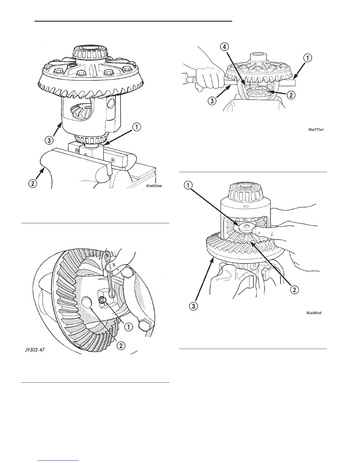
(4) Remove the pinion gear mate shaft lock screw
(Fig. 58).
(5) Remove the pinion gear mate shaft. If neces-
sary, use a drift and hammer (Fig. 59).
(6) Install and lubricate Step Plate 8139-2 (Fig.
60).
(7) Assemble Threaded Adapter 8139-1 into top
side gear. Thread Forcing Screw C-4487-2 into
adapter until it becomes centered in adapter plate.
(8) Position a small screw driver in slot of
Threaded Adapter 8139-1 (Fig. 61) to prevent adapter
from turning.
(9) Tighten forcing screw tool 122 N·m (90 ft. lbs.)
maximum to compress Belleville springs in clutch
packs (Fig. 62).
(10) Using an appropriate size feeler gauge,
remove thrust washers from behind the pinion gears
(Fig. 63).
(11) Insert Turning Bar C-4487-4 in case (Fig. 64).
Fig. 57 Differential Case Holding Tool
1 – SIDE GEAR HOLDING TOOL
2 – VISE
3 – DIFFERENTIAL
Fig. 58 Mate Shaft Lock Screw
1 – LOCK SCREW
2 – PINION GEAR MATE SHAFT
Fig. 59 Mate Shaft Removal
1 – PINION MATE SHAFT
2 – SIDE GEAR
3 – DRIFT
4 – PINION MATE GEAR
Fig. 60 Step Plate Tool Installation
1 – SPECIAL TOOL 8139–2
2 – LOWER SIDE GEAR
3 – DIFFERENTIAL CASE
DN 8 1/4 AND 9 1/4 AXLE 3 - 87
DISASSEMBLY AND ASSEMBLY (Continued)