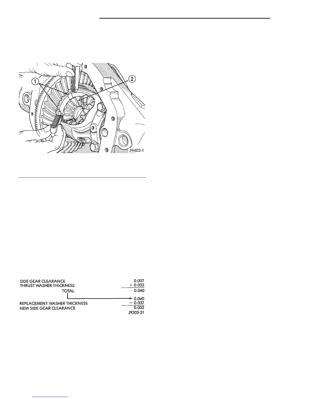
(2) Measure each side gear clearance. Insert a
matched pair of feeler gauge blades between the gear
and differential housing on opposite sides of the hub
(Fig. 82).
(3) If side gear clearances is no more than 0.005
inch. Determine if the axle shaft is contacting the
pinion mate shaft. Do not remove the feeler
gauges, inspect the axle shaft with the feeler
gauge inserted behind the side gear. If the end of
the axle shaft is not contacting the pinion mate
shaft, the side gear clearance is acceptable.
(4) If clearance is more than 0.005 inch (axle shaft
not contacting mate shaft), record the side gear clear-
ance. Remove the thrust washer and measure its
thickness with a micrometer. Add the washer thick-
ness to the recorded side gear clearance. The sum of
gear clearance and washer thickness will determine
required thickness of replacement thrust washer
(Fig. 83).
In some cases, the end of the axle shaft will move
and contact the mate shaft when the feeler gauge is
inserted. The C-lock is preventing the side gear from
sliding on the axle shaft.
(5) If there is no side gear clearance, remove the
C-lock from the axle shaft. Use a micrometer to mea-
sure the thrust washer thickness. Record the thick-
ness and re-install the thrust washer. Assemble the
differential case without the C-lock installed and re-
measure the side gear clearance.
(6) Compare both clearance measurements. If the
difference is less than 0.012 inch (0.305 mm), add
clearance recorded when the C-lock was installed to
thrust washer thickness measured. The sum will
determine the required thickness of the replacement
thrust washer.
(7) If clearance is 0.012 inch (0.305 mm) or
greater, both side gears must be replaced (matched
set) and the clearance measurements repeated.
(8) If clearance (above) continues to be 0.012 inch
(0.305 mm) or greater, the case must be replaced.
SPECIFICATIONS
8 1/4 INCH AXLE
Axle Type ............... Semi-floating, hypoid
Lubricant ...................... SAE80W-90
Lube Capacity ................ 2.22 L (4.7 pts.)
Trac-Lok Additive ............... 148ml(5oz.)
Axle Ratio .................... 3.21, 3.55, 3.92
Differential
Case Clearance ............. 0.12 mm (0.005 in.)
Case Flange Runout ........ 0.076 mm (0.003 in.)
Ring Gear
Diameter .................. 20.95 cm (8.25 in.)
Backlash ......... 0.12-0.20 mm (0.005-0.008 in.)
Runout .................. 0.127 mm (0.005 in.)
Pinion Bearing Preload
Original ................ 1-2N·m(10-20 in.lbs.)
New................... 2-5N·m(15-35 in.lbs.)
9 1/4 INCH AXLE
Axle Type ............... Semi-floating, hypoid
Lubricant ...................... SAE75W-90
Lube Capacity ................ 2.32 L (4.9 pts.)
Trac-lok Additive ................ 148ml(5oz.)
Axle Ratio .................... 3.21, 3.55, 3.92
Differential
Case Flange Runout ........ 0.076 mm (0.003 in.)
Ring gear
Diameter .................. 23.50 cm (9.25 in.)
Backlash ......... 0.12-0.20 mm (0.005-0.008 in.)
Runout .................. 0.127 mm (0.005 in.)
Pinion Bearing Preload
Original ................ 1-2N·m(10-20 in.lbs.)
New.................. 2–5N·m(15–35 in. lbs.)
Fig. 82 Side Gear Clearance Measurement
1 – FEELER GAUGE BLADES
2 – SIDE GEAR
Fig. 83 Side Gear Calculations
3 - 98 8 1/4 AND 9 1/4 AXLE DN
ADJUSTMENTS (Continued)