This sync signal generator detects a rotating pulse
ring (shutter) on the distributor shaft. The pulse ring
rotates 180 degrees through the sync signal genera-
tor. Its signal is used in conjunction with the Crank-
shaft Position (CKP) sensor to differentiate between
fuel injection and spark events. It is also used to syn-
chronize the fuel injectors with their respective cylin-
ders.
When the leading edge of the pulse ring (shutter)
enters the sync signal generator, the following occurs:
The interruption of magnetic field causes the voltage
to switch high resulting in a sync signal of approxi-
mately 5 volts.
When the trailing edge of the pulse ring (shutter)
leaves the sync signal generator, the following occurs:
The change of the magnetic field causes the sync sig-
nal voltage to switch low to 0 volts.
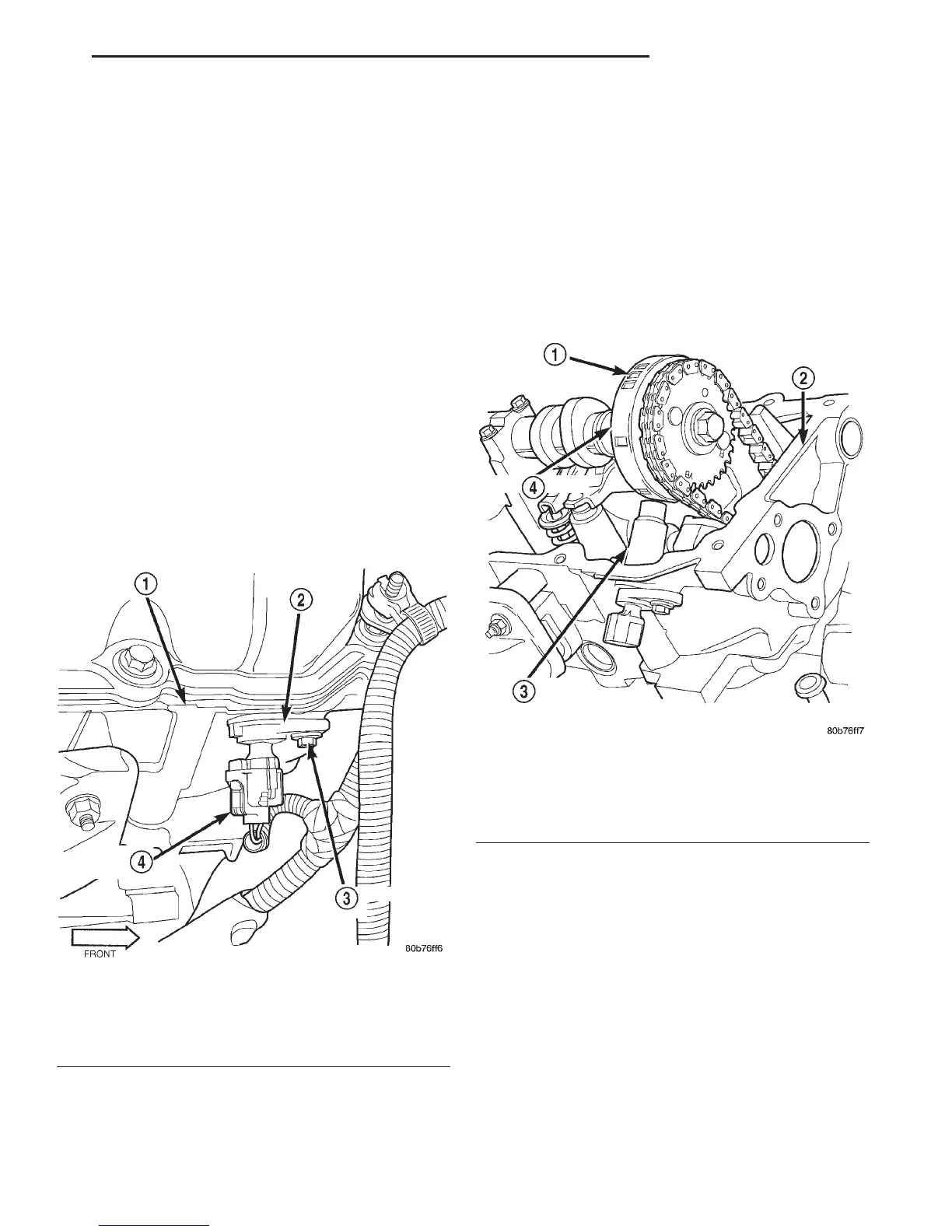
CAMSHAFT POSITION SENSOR—4.7L ENGINE
DESCRIPTION
The Camshaft Position Sensor (CMP) on the 4.7L
V–8 engine is bolted to the front/top of the right cyl-
inder head (Fig. 7).
OPERATION
The CMP sensor contains a hall effect device called
a sync signal generator to generate a fuel sync sig-
nal. This sync signal generator detects notches
located on a tonewheel. The tonewheel is located at
the front of the camshaft for the right cylinder head
(Fig. 8). As the tonewheel rotates, the notches pass
through the sync signal generator. The pattern of the
notches (viewed counter-clockwise from front of
engine) is: 1 notch, 2 notches, 3 notches, 3 notches, 2
notches 1 notch, 3 notches and 1 notch. The signal
from the CMP sensor is used in conjunction with the
crankshaft position sensor to differentiate between
fuel injection and spark events. It is also used to syn-
chronize the fuel injectors with their respective cylin-
ders.
IGNITION SWITCH AND KEY LOCK CYLINDER
DESCRIPTION
The electrical ignition switch is located on the
steering column. It is used as the main on/off switch-
ing device for most electrical components. The
mechanical key lock cylinder is used to engage/disen-
gage the electrical ignition switch.
OPERATION
Vehicles equipped with an automatic trans-
mission and a floor mounted shifter: a cable is
used to connect the interlock device in the steering
column assembly, to the transmission floor shift
lever. This interlock device is used to lock the trans-
mission shifter in the PARK position when the key
Fig. 7 CMP Location—4.7L Engine
1 – RIGHT CYLINDER HEAD
2 – CAMSHAFT POSITION SENSOR
3 – MOUNTING BOLT
4 – ELEC. CONNECTOR
Fig. 8 CMP Sensor and Tonewheel—4.7L Engine
1 – NOTCHES
2 – RIGHT CYLINDER HEAD
3 – CAMSHAFT POSITION SENSOR
4 – TONEWHEEL
DN IGNITION SYSTEM 8D - 5
DESCRIPTION AND OPERATION (Continued)