OPERATION
Engine speed and crankshaft position are provided
through the crankshaft position sensor. The sensor
generates pulses that are the input sent to the pow-
ertrain control module (PCM). The PCM interprets
the sensor input to determine the crankshaft posi-
tion. The PCM then uses this position, along with
other inputs, to determine injector sequence and igni-
tion timing.
The sensor is a hall effect device combined with an
internal magnet. It is also sensitive to steel within a
certain distance from it.
On the 4.7L V–8 engine, a tonewheel is bolted to
the engine crankshaft (Fig. 6). This tonewheel has
sets of notches at its outer edge (Fig. 6).
The notches cause a pulse to be generated when
they pass under the sensor. The pulses are the input
to the PCM.
CAMSHAFT POSITION SENSOR
DESCRIPTION
The Camshaft Position (CMP) sensor is located in
the distributor.
OPERATION
The sensor contains a hall effect device called a
sync signal generator to generate a fuel sync signal.
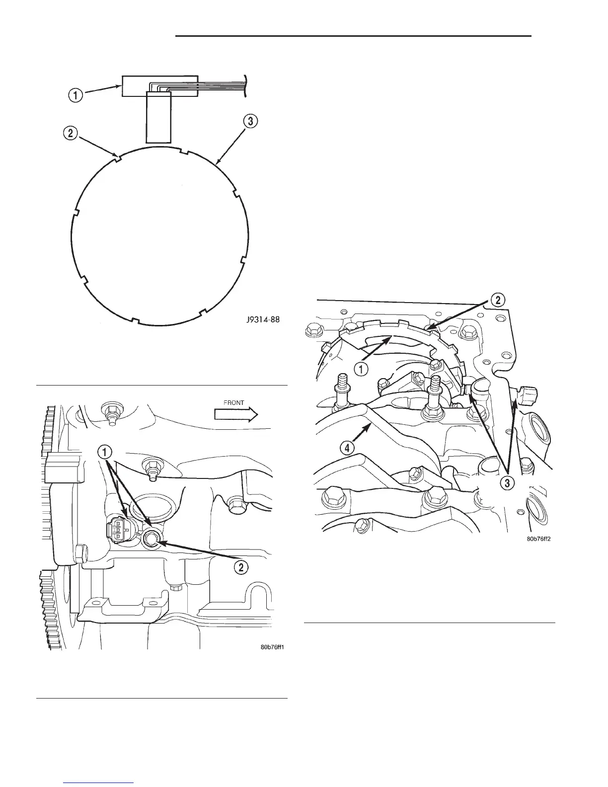
Fig. 4 CKP Sensor Operation—5.2L/5.9L Engine
1 – CRANKSHAFT POSITION SENSOR
2 – NOTCHES
3 – FLYWHEEL
Fig. 5 CKP Sensor Location—4.7L V–8 Engine
1 – CRANKSHAFT POSITION SENSOR
2 – MOUNTING BOLT
Fig. 6 CKP Sensor Operation and Tonewheel—4.7L
V–8 Engine
1 – TONEWHEEL
2 – NOTCHES
3 – CRANKSHAFT POSITION SENSOR
4 – CRANKSHAFT
8D - 4 IGNITION SYSTEM DN
DESCRIPTION AND OPERATION (Continued)