HEADLAMP SWITCH
WARNING: ON VEHICLES EQUIPPED WITH AIR-
BAGS, REFER TO GROUP 8M - PASSIVE
RESTRAINT SYSTEMS BEFORE ATTEMPTING ANY
STEERING WHEEL, STEERING COLUMN, OR
INSTRUMENT PANEL COMPONENT DIAGNOSIS OR
SERVICE. FAILURE TO TAKE THE PROPER PRE-
CAUTIONS COULD RESULT IN ACCIDENTAL AIR-
BAG DEPLOYMENT AND POSSIBLE PERSONAL
INJURY.
REMOVAL
(1) Disconnect and isolate the battery negative
cable.
(2) Remove the cluster bezel from the instrument
panel. Refer to Cluster Bezel in the Removal and
Installation section of this group for the procedures.
(3) Remove the three screws that secure the head-
lamp switch to the instrument panel (Fig. 2).
(4) Pull the headlamp switch away from the
instrument panel far enough to access the instru-
ment panel wire harness connectors.
(5) Disconnect the two instrument panel wire har-
ness connectors from the headlamp switch connector
receptacles.
(6) Remove the headlamp switch from the instru-
ment panel.
INSTALLATION
(1) Position the headlamp switch to the instru-
ment panel.
(2) Reconnect the two instrument panel wire har-
ness connectors to the headlamp switch connector
receptacles.
(3) Install the headlamp switch into the instru-
ment panel.
(4) Install and tighten the three screws that secure
the headlamp switch to the instrument panel.
Tighten the screws to 2.2 N·m (20 in. lbs.).
(5) Install the cluster bezel onto the instrument
panel. Refer to Cluster Bezel in the Removal and
Installation section of this group for the procedures.
(6) Reconnect the battery negative cable.
INSTRUMENT CLUSTER
WARNING: ON VEHICLES EQUIPPED WITH AIR-
BAGS, REFER TO GROUP 8M - PASSIVE
RESTRAINT SYSTEMS BEFORE ATTEMPTING ANY
STEERING WHEEL, STEERING COLUMN, OR
INSTRUMENT PANEL COMPONENT DIAGNOSIS OR
SERVICE. FAILURE TO TAKE THE PROPER PRE-
CAUTIONS COULD RESULT IN ACCIDENTAL AIR-
BAG DEPLOYMENT AND POSSIBLE PERSONAL
INJURY.
REMOVAL
(1) Disconnect and isolate the battery negative
cable.
(2) Remove the cluster bezel from the instrument
panel. Refer to Cluster Bezel in the index of this
service manual for the location of the proper cluster
bezel removal procedures.
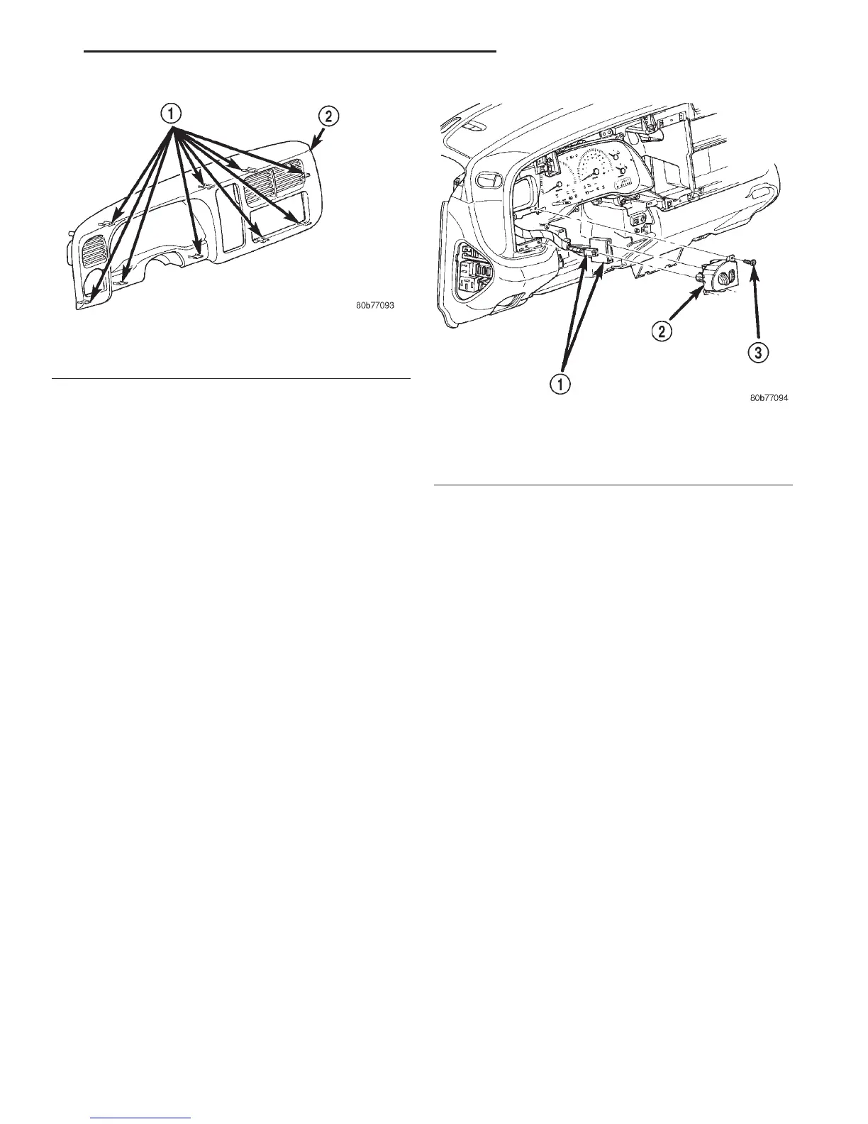
Fig. 1 Cluster Bezel Remove/Install
1 – SNAP CLIP RETAINERS
2 – CLUSTER BEZEL
Fig. 2 Headlamp Switch Remove/Install
1 – INSTRUMENT PANEL WIRE HARNESS CONNECTORS
2 – HEADLAMP SWITCH
3 – SCREW (3)
DN INSTRUMENT PANEL SYSTEMS 8E - 13
REMOVAL AND INSTALLATION (Continued)