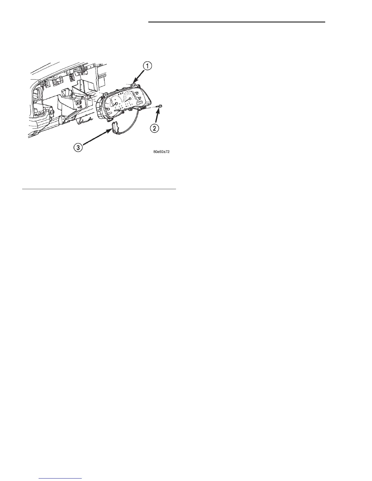
(3) Remove the four screws that secure the instru-
ment cluster to the instrument panel (Fig. 3).
(4) Place the automatic transmission gear selector
lever in the Park position.
(5) Pull the instrument cluster rearward far
enough to disengage the two self-docking instrument
panel wire harness connectors from the connector
receptacles on the back of the cluster housing.
(6) If the vehicle is equipped with a mechanical
automatic transmission gear selector indicator,
remove the gear selector indicator from the back of
the cluster housing. Refer to Gear Selector Indica-
tor in the index of this service manual for the loca-
tion of the proper gear selector indicator removal
procedures.
(7) Remove the instrument cluster from the instru-
ment panel.
INSTALLATION
(1) Position the instrument cluster to the instru-
ment panel.
(2) If the vehicle is equipped with a mechanical
automatic transmission gear selector indicator,
install the gear selector indicator onto the back of the
cluster housing. Refer to Gear Selector Indicator
in the index of this service manual for the location of
the proper gear selector indicator installation proce-
dures.
(3) Align the instrument cluster with the cluster
opening in the instrument panel and push the cluster
firmly and evenly into place. The instrument panel
has two self-docking wire harness connectors that
will be automatically aligned with, and connected to
the cluster connector receptacles when the cluster is
installed in the instrument panel.
(4) Install and tighten the four screws that secure
the instrument cluster to the instrument panel.
Tighten the screws to 2.2 N·m (20 in. lbs.).
(5) Install the cluster bezel onto the instrument
panel. Refer to Cluster Bezel in the index of this
service manual for the location of the proper cluster
bezel installation procedures.
(6) Reconnect the battery negative cable.
NOTE: Certain indicator lamps in this instrument
cluster are programmable. This feature allows those
indicator lamps to be activated or deactivated with
a DRBIIIT scan tool through the instrument cluster
electronic circuitry for compatibility with certain
optional equipment. If a new instrument cluster is
being installed, use a DRBIIIT scan tool to program
the instrument cluster with the proper vehicle
equipment option settings to activate and/or deacti-
vate the cruise-on indicator lamp, the overdrive-off
indicator lamp, the transmission oil temperature
warning lamp, and the upshift indicator lamp.
INSTRUMENT CLUSTER COMPONENTS
Some of the components for the instrument cluster
used in this vehicle are serviced individually. The
serviced components include: the incandescent
instrument cluster indicator lamp and illumination
lamp bulbs (including the integral bulb holders), the
cluster lens and hood unit, the instrument cluster
housing rear cover, and the instrument cluster hous-
ing (including the trip odometer reset knob, the clus-
ter mask, the gauges and the instrument cluster
electronic circuit board). Following are the service
procedures for the instrument cluster components.
WARNING: ON VEHICLES EQUIPPED WITH AIR-
BAGS, REFER TO GROUP 8M - PASSIVE
RESTRAINT SYSTEMS BEFORE ATTEMPTING ANY
STEERING WHEEL, STEERING COLUMN, OR
INSTRUMENT PANEL COMPONENT DIAGNOSIS OR
SERVICE. FAILURE TO TAKE THE PROPER PRE-
CAUTIONS COULD RESULT IN ACCIDENTAL AIR-
BAG DEPLOYMENT AND POSSIBLE PERSONAL
INJURY.
REMOVAL
CLUSTER BULB
This procedure applies to each of the incandescent
cluster illumination lamp or indicator lamp bulb and
bulb holder units. However, the illumination lamps
and the indicator lamps use different bulb and bulb
holder unit sizes. They must never be interchanged.
Be certain that any bulb and bulb holder unit
removed from the cluster electronic circuit board is
Fig. 3 Instrument Cluster Remove/Install
1 – CLUSTER
2 – SCREW
3 – PRNDL ADJUSTER AND CABLE
8E - 14 INSTRUMENT PANEL SYSTEMS DN
REMOVAL AND INSTALLATION (Continued)