reinstalled in the correct position. Always use the
correct bulb size and type for replacement. An incor-
rect bulb size or type may overheat and cause dam-
age to the instrument cluster, the electronic circuit
board and/or the gauges.
(1) Disconnect and isolate the battery negative
cable.
(2) Remove the instrument cluster from the instru-
ment panel. Refer to Instrument Cluster in the
Removal and Installation section of this group for the
procedures.
(3) Turn the bulb holder counterclockwise about
sixty degrees on the cluster electronic circuit board.
(4) Pull the bulb and bulb holder unit straight
back to remove it from the bulb mounting hole in the
cluster electronic circuit board (Fig. 4).
CLUSTER LENS AND HOOD
(1) Disconnect and isolate the battery negative
cable.
(2) Remove the instrument cluster from the instru-
ment panel. Refer to Instrument Cluster in the
Removal and Installation section of this group for the
procedures.
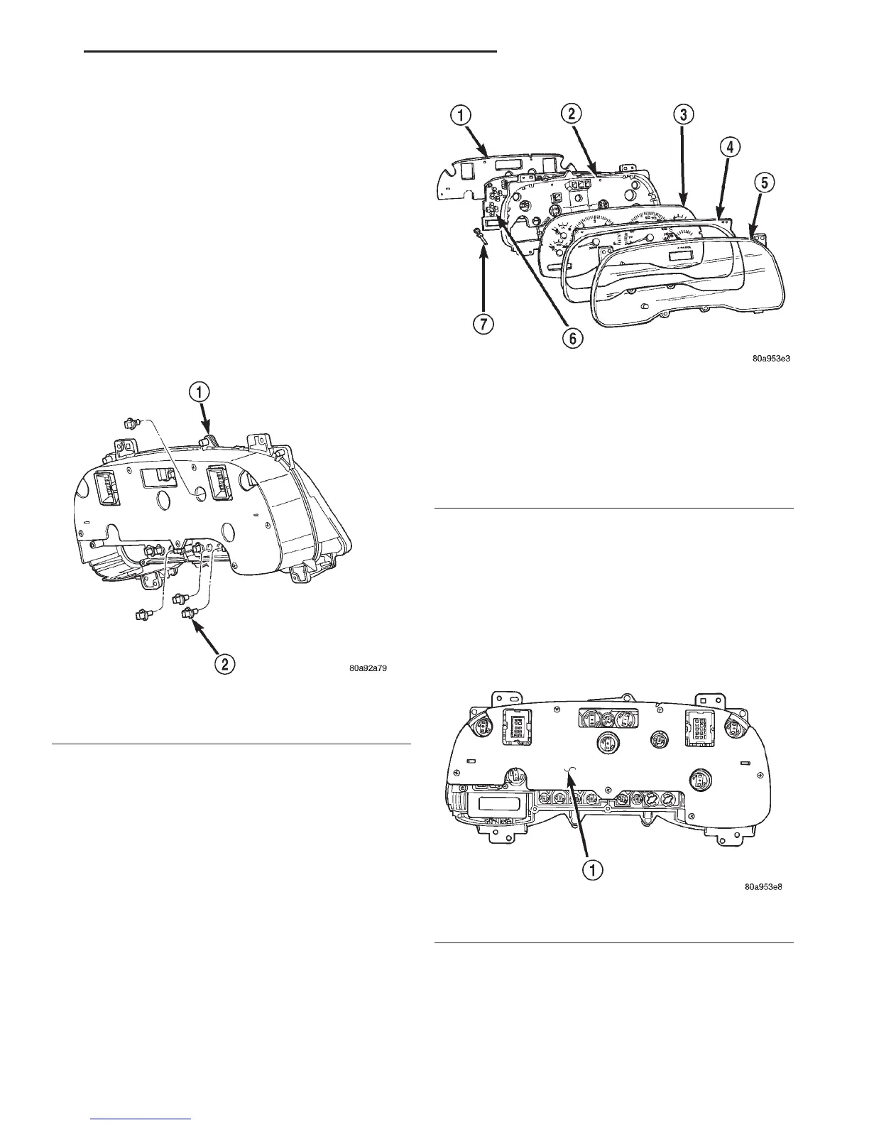
(3) Remove the seven screws that secure the lens
and hood unit to the cluster housing (Fig. 5).
(4) Gently pull the lens and hood unit away from
the cluster housing.
CAUTION: Do not touch the face of the gauge mask
or the back of the cluster lens with your finger. It
will leave a permanent finger print.
CLUSTER HOUSING REAR COVER
(1) Disconnect and isolate the battery negative
cable.
(2) Remove the instrument cluster from the instru-
ment panel. Refer to Instrument Cluster in the
Removal and Installation section of this group for the
procedures.
(3) Remove the six screws that secure the rear
cover to the back of the cluster housing (Fig. 6).
(4) Remove the rear cover from the back of the
cluster housing.
CLUSTER HOUSING
(1) Disconnect and isolate the battery negative
cable.
Fig. 4 Cluster Bulb Remove/Install
1 – INSTRUMENT CLUSTER
2 – BULB AND HOLDER
Fig. 5 Instrument Cluster Components
1 – COVER
2 – HOUSING
3 – MASK AND GAUGES
4 – HOOD
5 – LENS
6 – CIRCUIT BOARD
7 – ODOMETER RESET BUTTON
Fig. 6 Cluster Housing Rear Cover Remove/Install
1 – REAR CLUSTER HOUSING COVER
DN INSTRUMENT PANEL SYSTEMS 8E - 15
REMOVAL AND INSTALLATION (Continued)