REMOVAL
(1) Disconnect and isolate the battery negative
cable.
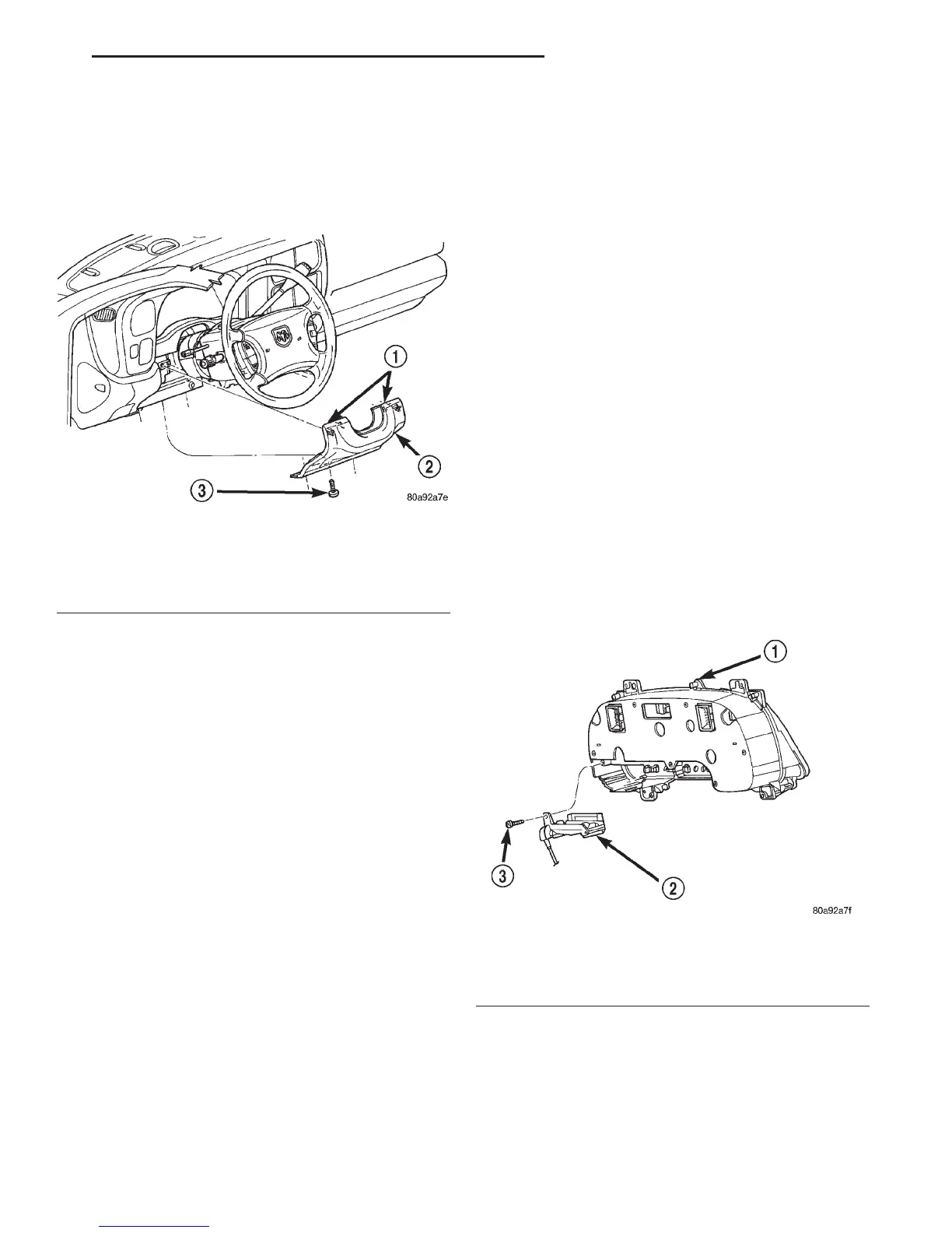
(2) Remove the three screws that secure the lower
edge of the steering column opening cover to the
lower instrument panel reinforcement (Fig. 7).
(3) Using a trim stick or another suitable wide
flat-bladed tool, gently pry the upper edge of the
steering column opening cover just below the cluster
bezel on each side of the steering column away from
the instrument panel far enough to disengage the
snap clip retainers from the receptacles in the instru-
ment panel.
(4) Remove the steering column opening cover
from the instrument panel.
INSTALLATION
(1) Position the steering column opening cover to
the instrument panel.
(2) Align the snap clip retainers on the steering
column opening cover with the receptacles in the
instrument panel.
(3) Press firmly on the steering column opening
cover over the snap clip locations until each of the
snap clips is fully engaged in its receptacle.
(4) Install and tighten the three screws that secure
the lower edge of the steering column opening cover
to the lower instrument panel reinforcement. Tighten
the screws to 2.2 N·m (20 in. lbs.).
(5) Reconnect the battery negative cable.
GEAR SELECTOR INDICATOR
The following service procedures apply only to the
mechanical gear selector indicator. The electronic
gear selector indicator is integral to the instrument
cluster and can only be serviced by replacement of
the instrument cluster unit.
WARNING: ON VEHICLES EQUIPPED WITH AIR-
BAGS, REFER TO GROUP 8M - PASSIVE
RESTRAINT SYSTEMS BEFORE ATTEMPTING ANY
STEERING WHEEL, STEERING COLUMN, OR
INSTRUMENT PANEL COMPONENT DIAGNOSIS OR
SERVICE. FAILURE TO TAKE THE PROPER PRE-
CAUTIONS COULD RESULT IN ACCIDENTAL AIR-
BAG DEPLOYMENT AND POSSIBLE PERSONAL
INJURY.
REMOVAL
(1) Disconnect and isolate the battery negative
cable.
(2) Remove the instrument cluster from the instru-
ment panel. Refer to Instrument Cluster in the
Removal and Installation section of this group for the
procedures.
(3) Remove the two screws that secure the gear
selector indicator mechanism to the back of the
instrument cluster housing (Fig. 8).
(4) Remove the gear selector indicator mechanism
from the back of the instrument cluster housing.
Fig. 7 Steering Column Opening Cover Remove/
Install
1 – SNAP CLIPS
2 – COVER
3 – SCREW
Fig. 8 Gear Selector Indicator Remove/Install
1 – INSTRUMENT CLUSTER
2 – GEAR SELECTOR INDICATOR
3 – SCREW
DN INSTRUMENT PANEL SYSTEMS 8E - 17
REMOVAL AND INSTALLATION (Continued)