(5) Remove the steering column opening cover
from the instrument panel. Refer to Steering Col-
umn Opening Cover in the Removal and Installa-
tion section of this group for the procedures.
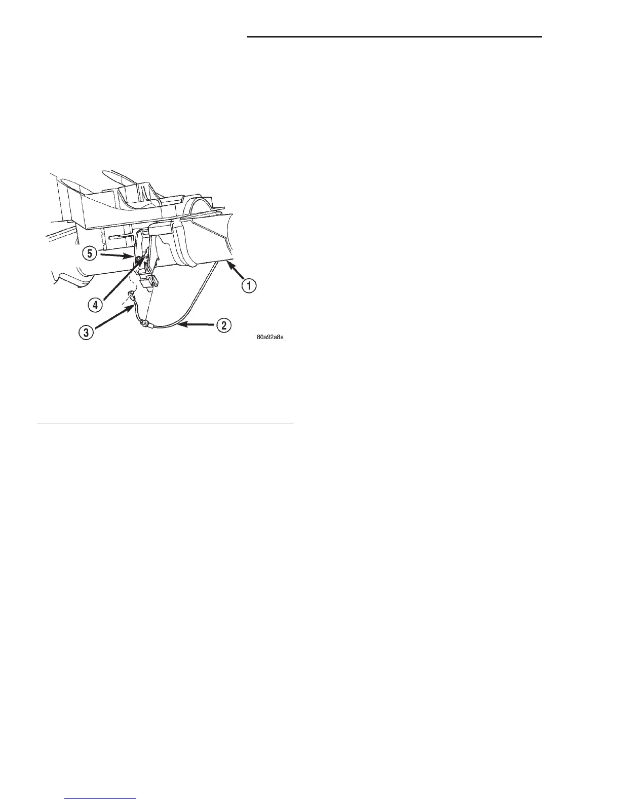
(6) Disengage the loop end of the gear selector
indicator cable from the lever on the left side of the
steering column (Fig. 9).
(7) Squeeze the sides of the plastic adjuster and
bracket unit to disengage the tabs that secure it to
the sides of the steering column window.
(8) Remove the gear selector indicator mechanism
and cable unit from the instrument panel.
INSTALLATION
(1) Position the gear selector indicator mechanism
and cable unit to the instrument panel.
(2) Squeeze the sides of the plastic adjuster and
bracket unit and engage the tabs that secure it with
the sides of the steering column window.
(3) Engage the loop end of the gear selector indi-
cator cable onto the lever on the left side of the steer-
ing column (Fig. 9).
(4) Position the gear selector indicator mechanism
onto the back of the instrument cluster housing.
(5) Install and tighten the two screws that secure
the gear selector indicator mechanism to the back of
the instrument cluster housing. Tighten the screws
to 2.2 N·m (20 in. lbs.).
(6) Install the instrument cluster onto the instru-
ment panel. Refer to Instrument Cluster in the
Removal and Installation section of this group for the
procedures.
(7) Check the gear selector indicator for proper cal-
ibration. If adjustment is needed, refer to Steering
Column in the Removal and Installation section of
Group 19 - Steering for the gear selector indicator
cable (PRNDL) adjustment procedure.
(8) Install the steering column opening cover onto
the instrument panel. Refer to Steering Column
Opening Cover in the Removal and Installation sec-
tion of this group for the procedures.
(9) Reconnect the battery negative cable.
PARK BRAKE RELEASE HANDLE
WARNING: ON VEHICLES EQUIPPED WITH AIR-
BAGS, REFER TO GROUP 8M - PASSIVE
RESTRAINT SYSTEMS BEFORE ATTEMPTING ANY
STEERING WHEEL, STEERING COLUMN, OR
INSTRUMENT PANEL COMPONENT DIAGNOSIS OR
SERVICE. FAILURE TO TAKE THE PROPER PRE-
CAUTIONS COULD RESULT IN ACCIDENTAL AIR-
BAG DEPLOYMENT AND POSSIBLE PERSONAL
INJURY.
REMOVAL
(1) Disconnect and isolate the battery negative
cable.
(2) Reach under the driver side outboard end of
the instrument panel to access and unsnap the plas-
tic retainer clip that secures the park brake release
linkage rod to the lever on the back side of the park
brake release handle.
(3) Disengage the park brake release linkage rod
end from the lever on the back of the park brake
release handle.
(4) Using a trim stick or another suitable wide
flat-bladed tool, gently pry one of the park brake
handle hinge tabs away from its pivot pin on the
instrument panel (Fig. 10).
(5) While prying the park brake release handle
hinge tab with one hand, use the other hand to pull
the handle firmly down and away from the pivot pin.
(6) Remove the park brake release handle from the
instrument panel.
INSTALLATION
(1) Position the park brake release handle to the
instrument panel.
(2) Engage one of the park brake release handle
hinge tabs with one of the pivot pins on the instru-
ment panel.
(3) Align the second park brake release handle
hinge tab hinge over the second pivot pin on the
instrument panel.
(4) Press firmly on the park brake release handle
over the second hinge tab until it snaps over the sec-
ond pivot pin on the instrument panel.
Fig. 9 Gear Selector Indicator Cable Remove/Install
1 – STEERING COLUMN
2 – CABLE
3 – LOOP END
4 – LEVER
5 – ADJUSTER AND BRACKET
8E - 18 INSTRUMENT PANEL SYSTEMS DN
REMOVAL AND INSTALLATION (Continued)