(5) Reach under the driver side outboard end of
the instrument panel to access and engage the park
brake release linkage rod end from the lever on the
back of the park brake release handle.
(6) Snap the plastic retainer clip that secures the
park brake release linkage rod to the lever on the
back side of the park brake release handle over the
linkage rod.
(7) Reconnect the battery negative cable.
INSTRUMENT PANEL LOWER
REINFORCEMENT
WARNING: ON VEHICLES EQUIPPED WITH AIR-
BAGS, REFER TO GROUP 8M - PASSIVE
RESTRAINT SYSTEMS BEFORE ATTEMPTING ANY
STEERING WHEEL, STEERING COLUMN, OR
INSTRUMENT PANEL COMPONENT DIAGNOSIS OR
SERVICE. FAILURE TO TAKE THE PROPER PRE-
CAUTIONS COULD RESULT IN ACCIDENTAL AIR-
BAG DEPLOYMENT AND POSSIBLE PERSONAL
INJURY.
REMOVAL
(1) Disconnect and isolate the battery negative
cable.
(2) Remove the steering column opening cover
from the instrument panel. Refer to Steering Col-
umn Opening Cover in the Removal and Installa-
tion section of this group for the procedures.
(3) Remove the two screws that secure the inside
hood latch release handle to the instrument panel
lower reinforcement and lower the release handle to
the floor.
(4) Depress the latch tabs that secure the 16-way
data link wire harness connector to the instrument
panel lower reinforcement, and push the connector
out of its mounting hole.
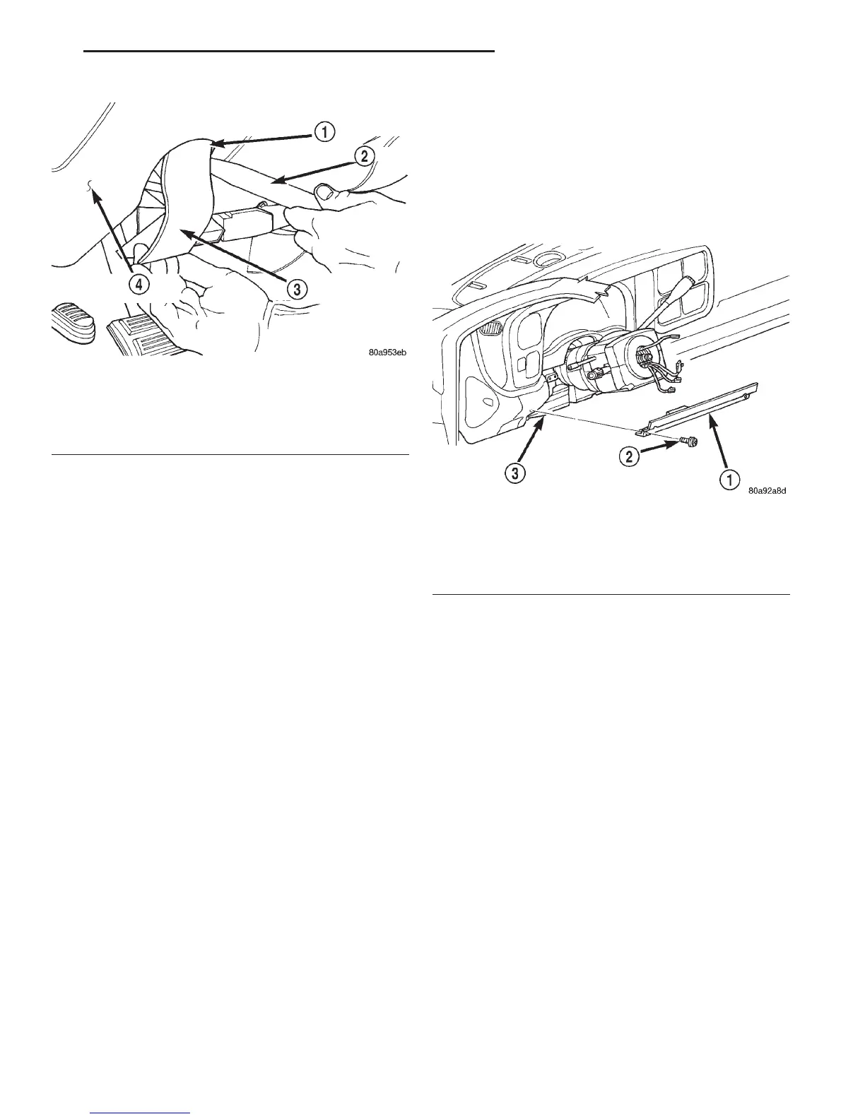
(5) Remove the four screws that secure the lower
reinforcement to the instrument panel (Fig. 11).
(6) Remove the lower reinforcement from the
instrument panel.
INSTALLATION
(1) Position the lower reinforcement onto the
instrument panel.
(2) Install and tighten the four screws that secure
the lower reinforcement to the instrument panel.
Tighten the screws to 2.2 N·m (20 in. lbs.).
(3) Install the 16-way data link wire harness con-
nector into the mounting hole on the instrument
panel lower reinforcement.
(4) Position the inside hood latch release handle to
the instrument panel lower reinforcement.
(5) Install and tighten the two screws that secure
the inside hood latch release handle to the instru-
ment panel lower reinforcement. Tighten the screws
to 2.8 N·m (25 in. lbs.).
(6) Install the steering column opening cover onto
the instrument panel. Refer to Steering Column
Opening Cover in the Removal and Installation sec-
tion of this group for the procedures.
(7) Reconnect the battery negative cable.
Fig. 10 Park Brake Release Handle Remove/Install
1 – INSERT BETWEEN HINGE TAB AND PIVOT PIN
2 – TRIM STICK
3 – PARK BRAKE RELEASE HANDLE
4 – INSTRUMENT PANEL
Fig. 11 Instrument Panel Lower Reinforcement
Remove/Install
1 – REINFORCEMENT
2 – SCREW
3 – INSTRUMENT PANEL
DN INSTRUMENT PANEL SYSTEMS 8E - 19
REMOVAL AND INSTALLATION (Continued)