(3) Remove the two screws that secure the latch
striker to the instrument panel glove box opening
upper reinforcement (Fig. 18).
(4) Remove the latch striker from the instrument
panel glove box opening upper reinforcement.
INSTALLATION
(1) Position the latch striker onto the instrument
panel glove box opening upper reinforcement.
(2) Install and tighten the two screws that secure
the latch striker to the instrument panel glove box
opening upper reinforcement. Tighten the screws to
2.2 N·m (20 in. lbs.).
(3) Close the glove box.
(4) Reconnect the battery negative cable.
GLOVE BOX
WARNING: ON VEHICLES EQUIPPED WITH AIR-
BAGS, REFER TO GROUP 8M - PASSIVE
RESTRAINT SYSTEMS BEFORE ATTEMPTING ANY
STEERING WHEEL, STEERING COLUMN, OR
INSTRUMENT PANEL COMPONENT DIAGNOSIS OR
SERVICE. FAILURE TO TAKE THE PROPER PRE-
CAUTIONS COULD RESULT IN ACCIDENTAL AIR-
BAG DEPLOYMENT AND POSSIBLE PERSONAL
INJURY.
ROLL DOWN
(1) Disconnect and isolate the battery negative
cable.
(2) Open the glove box.
(3) Depress the two sides of the glove box bin far
enough so that the rubber stop bumpers located on
each side of the bin will clear the metal stops located
on the bracket on each side of the glove box opening.
(4) While holding the sides of the glove box bin
depressed, roll the glove box downward until the stop
bumpers are beyond the stops, then release the sides
of the bin.
(5) Reverse the roll down procedure to roll the
glove box back up into the instrument panel.
REMOVAL
(1) Disconnect and isolate the battery negative
cable.
(2) Open the glove box.
(3) Locate three screws in the bottom of the glove
box bin. Remove only the center screw.
(4) Roll down the glove box from the instrument
panel. Refer to Glove Box - Roll Down in the
Removal and Installation section of this group for the
procedures.
(5) Grasp the upper outboard corner of the glove
box door securely with both hands.
(6) Pull the door firmly and quickly away from the
instrument panel to unsnap the three glove box
hinge hooks (Fig. 19) from the three hinge pins on
the instrument panel (Fig. 20).
(7) Remove the glove box from the instrument
panel.
INSTALLATION
(1) Position the glove box to the instrument panel
with the bin inserted in the glove box opening far
enough so that the rubber stop bumpers located on
each side of the bin are behind the metal stops
located on the bracket on each side of the glove box
opening.
(2) Starting on the outboard side of the glove box,
insert the first glove box hinge hook over the first
hinge pin on the instrument panel.
Fig. 18 Glove Box Latch Striker Remove/Install
1 – SCREWS
2 – STRIKER
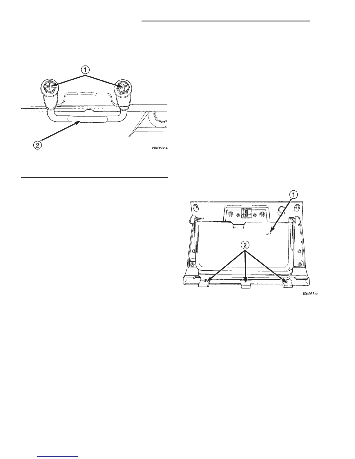
Fig. 19 Glove Box Hinge Hooks
1 – GLOVE BOX
2 – HINGE HOOKS
8E - 24 INSTRUMENT PANEL SYSTEMS DN
REMOVAL AND INSTALLATION (Continued)