(3) Use a slight twisting action on the glove box
door to insert the second hinge hook under the sec-
ond hinge pin.
(4) Finally, again using a slight twisting action on
the glove box door, insert the last hinge hook over
the last hinge pin.
(5) Install and tighten the center screw in the bot-
tom of the glove box bin. Tighten the screw to 2.2
N·m (20 in. lbs.).
(6) Close the glove box, then reopen it to check for
proper hinge operation.
(7) Reconnect the battery negative cable.
GLOVE BOX COMPONENTS
The only serviced component of the glove box is the
glove box bin. If any other component of the glove
box is faulty or damaged, the entire glove box assem-
bly must be replaced.
WARNING: ON VEHICLES EQUIPPED WITH AIR-
BAGS, REFER TO GROUP 8M - PASSIVE
RESTRAINT SYSTEMS BEFORE ATTEMPTING ANY
STEERING WHEEL, STEERING COLUMN, OR
INSTRUMENT PANEL COMPONENT DIAGNOSIS OR
SERVICE. FAILURE TO TAKE THE PROPER PRE-
CAUTIONS COULD RESULT IN ACCIDENTAL AIR-
BAG DEPLOYMENT AND POSSIBLE PERSONAL
INJURY.
REMOVAL
GLOVE BOX BIN
(1) Disconnect and isolate the battery negative
cable.
(2) Remove the glove box from the instrument
panel. Refer to Glove Box - Removal in the
Removal and Installation section of this group for the
procedures.
(3) Remove the two screws that secure each out-
board flange of the glove box bin to the glove box
door (Fig. 21).
(4) Remove the two remaining screws in the bot-
tom of the glove box bin (the center screw was
removed during glove box removal) that secure the
bin to the bottom of the glove box door.
(5) Remove the four screws that secure the top of
the glove box bin and the glove box latch to the glove
box door.
(6) Remove the glove box bin and the glove box
latch from the glove box door.
INSTALLATION
GLOVE BOX BIN
(1) Position the glove box latch and the glove box
bin to the glove box door.
(2) Install and tighten the four screws that secure
the top of the glove box bin and the glove box latch to
the glove box door. Tighten the screws to 2.2 N·m (20
in. lbs.).
(3) Install and tighten the two outboard screws in
the bottom of the glove box bin (the center screw will
be installed following glove box installation) that
secure the bin to the bottom of the glove box door.
Tighten the screws to 2.2 N·m (20 in. lbs.).
(4) Install and tighten the two screws that secure
each outboard flange of the glove box bin to the glove
box door. Tighten the screws to 2.2 N·m (20 in. lbs.).
(5) Install the glove box onto the instrument panel.
Refer to Glove Box - Installation in the Removal
and Installation section of this group for the proce-
dures.
(6) Reconnect the battery negative cable.
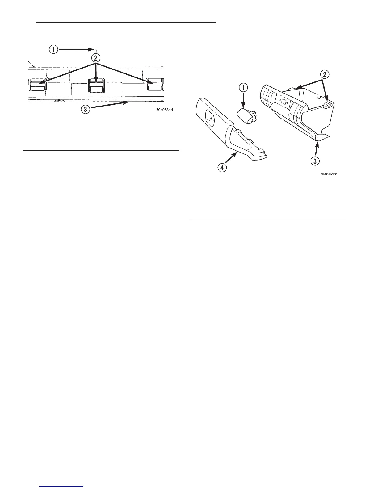
Fig. 20 Glove Box Hinge Pins
1 – GLOVE BOX OPENING
2 – HINGE PINS
3 – INSTRUMENT PANEL
Fig. 21 Glove Box Components Remove/Install
1–LATCH
2 – STOP BUMPERS
3 – BIN
4 – DOOR
DN INSTRUMENT PANEL SYSTEMS 8E - 25
REMOVAL AND INSTALLATION (Continued)