POWER AMPLIFIER
WARNING: ON VEHICLES EQUIPPED WITH AIR-
BAGS, REFER TO GROUP 8M - PASSIVE
RESTRAINT SYSTEMS BEFORE ATTEMPTING ANY
STEERING WHEEL, STEERING COLUMN, OR
INSTRUMENT PANEL COMPONENT DIAGNOSIS OR
SERVICE. FAILURE TO TAKE THE PROPER PRE-
CAUTIONS COULD RESULT IN ACCIDENTAL AIR-
BAG DEPLOYMENT AND POSSIBLE PERSONAL
INJURY.
REMOVAL
(1) Disconnect and isolate the battery negative
cable.
(2) Remove the trim cover from the right cowl side
inner panel. Refer to Cowl Trim Cover in the
Removal and Installation section of Group 23 - Body
for the procedures.
(3) Disconnect the two instrument panel wire har-
ness connectors from the connector receptacles on the
bottom of the power amplifier (Fig. 10).
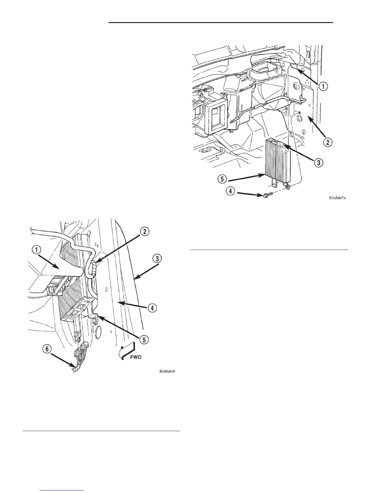
(4) Remove the two screws that secure the power
amplifier to the right cowl side inner panel (Fig. 11).
(5) To disengage the upper hook bracket of the
power amplifier from the upper hinge access hole in
the right cowl side inner panel:
(a) Lift the power amplifier upwards about 5
centimeters (2 inches).
(b) Tilt the top of the power amplifier toward the
instrument panel.
(c) Keep the top of the power amplifier tilted
toward the instrument panel while lowering the
unit from between the right cowl side inner panel
and the end of the heater-A/C housing.
(6) Remove the power amplifier from the right
cowl side inner panel.
INSTALLATION
(1) Position the power amplifier to the right cowl
side inner panel.
(2) To engage the upper hook bracket of the power
amplifier in the upper hinge access hole in the right
cowl side inner panel:
(a) Tilt the top of the power amplifier toward the
instrument panel.
(b) Keep the top of the power amplifier tilted
toward the instrument panel while lifting the unit
up between the right cowl side inner panel and the
end of the heater-A/C housing.
Fig. 10 Power Amplifier Connections Remove/Install
1 – HEATER-A/C HOUSING
2 – ANTENNA COAXIAL CABLE
3 – FENDER
4 – HINGE PILLAR
5 – AMPLIFIER
6 – WIRE HARNESS
Fig. 11 Power Amplifier Remove/Install
1 – UPPER HINGE ACCESS HOLE
2 – COWL SIDE INNER PANEL
3 – HOOK
4 – SCREW
5 – AMPLIFIER
8F - 14 AUDIO SYSTEMS DN
REMOVAL AND INSTALLATION (Continued)