(c) When the lower power amplifier mounting
brackets are about 5 centimeters (2 inches) above
the mounting holes for the lower brackets in the
right cowl side inner panel, tilt the top of the
power amplifier toward the right cowl side inner
panel.
(d) Lower the power amplifier until the upper
hook bracket is engaged in the upper hinge access
hole in the right cowl side inner panel. Tighten the
screws to 2 N·m (17 in. lbs.).
(3) Install and tighten the two screws that secure
the power amplifier to the right cowl side inner
panel.
(4) Reconnect the two instrument panel wire har-
ness connectors to the connector receptacles on the
bottom of the power amplifier.
(5) Install the trim cover onto the right cowl side
inner panel. Refer to Cowl Trim Cover in the
Removal and Installation section of Group 23 - Body
for the procedures.
(6) Reconnect the battery negative cable.
ANTENNA
WARNING: ON VEHICLES EQUIPPED WITH AIR-
BAGS, REFER TO GROUP 8M - PASSIVE
RESTRAINT SYSTEMS BEFORE ATTEMPTING ANY
STEERING WHEEL, STEERING COLUMN, OR
INSTRUMENT PANEL COMPONENT DIAGNOSIS OR
SERVICE. FAILURE TO TAKE THE PROPER PRE-
CAUTIONS COULD RESULT IN ACCIDENTAL AIR-
BAG DEPLOYMENT AND POSSIBLE PERSONAL
INJURY.
REMOVAL
ANTENNA BODY AND CABLE
(1) Disconnect and isolate the battery negative
cable.
(2) Remove the trim cover from the right cowl side
inner panel. Refer to Cowl Trim Cover in the
Removal and Installation section of Group 23 - Body
for the procedures.
(3) Reach under the instrument panel below the
glove box to access and disconnect the antenna coax-
ial cable connector (Fig. 12). Disconnect the connector
by pulling it apart while twisting the metal connector
halves. Do not pull on the cable.
(4) Disengage the antenna coaxial cable from the
retainer clips on the lower instrument panel rein-
forcement and the heater-A/C housing.
(5) Disengage the antenna coaxial cable retainers
at the right cowl side inner panel and inside the
right front fender.
(6) Unscrew the antenna mast from the antenna
body (Fig. 13).
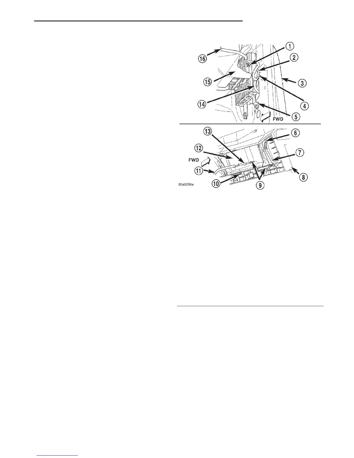
Fig. 12 Antenna Coaxial Cable Routing
1 – CLIP
2 – ANTENNA BODY AND CABLE
3 – RIGHT FRONT FENDER
4 – RETAINER
5 – AMPLIFIER
6 – TO RADIO
7 – COAXIAL CABLE
8 – INSTRUMENT PANEL
9 – CONNECTOR
10 – CLIP
11 – TO ANTENNA
12 – GLOVE BOX BIN
13 – ANTENNA BODY AND CABLE
14 – TO ANTENNA
15 – HEATER-A/C HOUSING
16 – TO RADIO
DN AUDIO SYSTEMS 8F - 15
REMOVAL AND INSTALLATION (Continued)