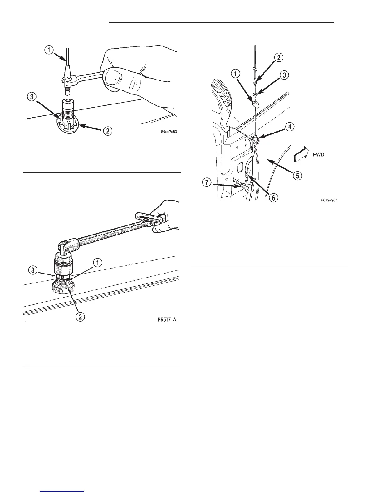
(7) Remove the antenna cap nut using an antenna
nut wrench (Special Tool C-4816) (Fig. 14).
(8) Remove the antenna adapter from the top of
the fender.
(9) Lower the antenna body through the mounting
hole in the top of the fender.
(10) Pull the antenna body and cable out through
the opening between the right cowl side outer panel
and the fender through the front door opening (Fig.
15).
(11) Disengage the antenna coaxial cable grommet
from the hole in the right cowl side outer panel.
(12) Pull the antenna coaxial cable out of the pas-
senger compartment through the hole in the right
cowl side outer panel.
(13) Remove the antenna body and cable from the
vehicle.
INSTRUMENT PANEL ANTENNA CABLE
(1) Disconnect and isolate the battery negative
cable.
(2) Reach under the instrument panel below the
glove box to access and disconnect the antenna coax-
ial cable connector (Fig. 12). Disconnect the connector
by pulling it apart while twisting the metal connector
halves. Do not pull on the cable.
(3) Securely tie a suitable length of cord or twine
to the instrument panel half of the antenna coaxial
cable connector. This cord will be used to pull or
“fish” the cable back into position during installation.
(4) Disengage the instrument panel antenna cable
from the retainer clip on the lower instrument panel
reinforcement inboard of the glove box opening.
(5) Roll down the glove box from the instrument
panel. Refer to Glove Box in the Removal and
Installation section of Group 8E - Instrument Panel
Systems for the procedures.
Fig. 13 Antenna Mast Remove/Install - Typical
1 – ANTENNA MAST
2 – ADAPTER
3 – CAP NUT
Fig. 14 Antenna Cap Nut and Adapter Remove/
Install - Typical
1 – CAP NUT
2 – ANTENNA ADAPTER
3–TOOL
Fig. 15 Antenna Mounting
1 – ADAPTER
2 – MAST
3 – NUT
4 – ANTENNA BODY AND CABLE
5 – RIGHT FRONT FENDER
6 – RETAINER
7 – GROMMET
8F - 16 AUDIO SYSTEMS DN
REMOVAL AND INSTALLATION (Continued)