REMOVAL AND INSTALLATION
HORN RELAY
WARNING: ON VEHICLES EQUIPPED WITH AIR-
BAGS, DISABLE THE AIRBAG SYSTEM BEFORE
ATTEMPTING ANY STEERING WHEEL, STEERING
COLUMN, OR INSTRUMENT PANEL COMPONENT
DIAGNOSIS OR SERVICE. DISCONNECT AND ISO-
LATE THE BATTERY NEGATIVE (GROUND) CABLE,
THEN WAIT TWO MINUTES FOR THE AIRBAG SYS-
TEM CAPACITOR TO DISCHARGE BEFORE PER-
FORMING FURTHER DIAGNOSIS OR SERVICE. THIS
IS THE ONLY SURE WAY TO DISABLE THE AIRBAG
SYSTEM. FAILURE TO TAKE THE PROPER PRE-
CAUTIONS COULD RESULT IN ACCIDENTAL AIR-
BAG DEPLOYMENT AND POSSIBLE PERSONAL
INJURY.
REMOVAL
(1) Disconnect and isolate the battery negative
cable.
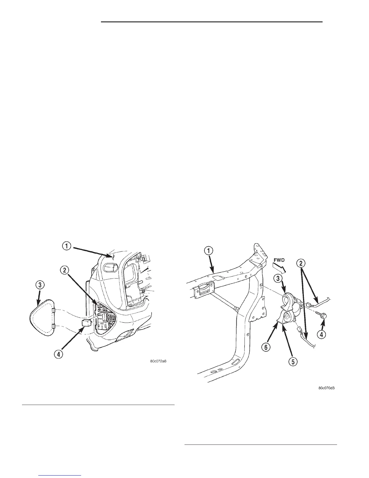
(2) Remove the fuse access panel by inserting a
finger in the finger recess molded into the panel and
then pulling the panel sharply away from the left
outboard end of the instrument panel (Fig. 2).
(3) See the fuse and relay layout label affixed to
the inside of the fuse access panel for horn relay
identification and location.
(4) Grasp the horn relay firmly and pull it straight
out from the JB.
INSTALLATION
(1) See the fuse and relay layout label affixed to
the inside of the fuse access panel for the proper
horn relay location.
(2) Position the horn relay in the proper receptacle
in the JB.
(3) Align the horn relay terminals with the termi-
nal cavities in the JB receptacle.
(4) Push in firmly on the horn relay until the ter-
minals are fully seated in the terminal cavities in the
JB receptacle.
(5) Insert the tabs on the forward edge of the fuse
access panel in the notches on the forward edge of
the instrument panel fuse access panel opening.
(6) Press the rear edge of the fuse access panel in
toward the instrument panel until the panel snaps
back into place.
(7) Reconnect the battery negative cable.
HORN
REMOVAL
(1) Disconnect and isolate the battery negative
cable.
(2) Disconnect the headlamp and dash wire har-
ness connectors from the horn connector receptacles
(Fig. 3).
Fig. 2 Horn Relay Remove/Install
1 – INSTRUMENT PANEL
2 – JUNCTION BLOCK
3 – FUSE ACCESS PANEL
4 – HORN RELAY
Fig. 3 Horns Remove/Install
1 – RADIATOR SUPPORT
2 – HEADLAMP AND DASH WIRE HARNESS
3 – LOW NOTE
4 – SCREW
5 – HORN AND BRACKET
6 – HIGH NOTE
8G - 4 HORN SYSTEMS DN