NOTE: When removing or installing the IOD fuse, it
is important that the ignition switch be in the Off
position. Failure to place the ignition switch in the
Off position can cause the radio display to become
scrambled when the IOD fuse is installed. Remov-
ing and installing the IOD fuse again with the igni-
tion switch in the Off position will usually correct
the scrambled radio display condition.
REMOVAL
(1) Turn the ignition switch to the Off position.
(2) Remove the fuse access panel by unsnapping it
from the left outboard end of the instrument panel.
(3) Grasp the upper and lower tabs of the IOD
fuse holder unit in fuse cavity 12 of the JB between
the thumb and forefinger and pull the unit firmly
outward.
(4) Install the fuse access panel by snapping it
onto the left outboard end of the instrument panel.
INSTALLATION
(1) Turn the ignition switch to the Off position.
(2) Remove the fuse access panel by unsnapping it
from the left outboard end of the instrument panel.
(3) To install the IOD fuse, use a thumb to press
the IOD fuse holder unit in fuse cavity 12 firmly into
the JB.
(4) Install the fuse access panel by snapping it
onto the left outboard end of the instrument panel.
RELAY AND FUSE BLOCK
The relay and fuse block is serviced as a unit with
the instrument panel wire harness. If any internal
circuit of the relay and fuse block or the relay and
fuse block housing is faulty or damaged, the entire
instrument panel wire harness unit must be
replaced.
WARNING: ON VEHICLES EQUIPPED WITH AIR-
BAGS, DISABLE THE AIRBAG SYSTEM BEFORE
ATTEMPTING ANY STEERING WHEEL, STEERING
COLUMN, OR INSTRUMENT PANEL COMPONENT
DIAGNOSIS OR SERVICE. DISCONNECT AND ISO-
LATE THE BATTERY NEGATIVE (GROUND) CABLE,
THEN WAIT TWO MINUTES FOR THE AIRBAG SYS-
TEM CAPACITOR TO DISCHARGE BEFORE PER-
FORMING FURTHER DIAGNOSIS OR SERVICE. THIS
IS THE ONLY SURE WAY TO DISABLE THE AIRBAG
SYSTEM. FAILURE TO TAKE THE PROPER PRE-
CAUTIONS COULD RESULT IN ACCIDENTAL AIR-
BAG DEPLOYMENT AND POSSIBLE PERSONAL
INJURY.
REMOVAL
(1) Disconnect and isolate the battery negative
cable.
(2) Remove the instrument panel assembly from
the dash panel. Refer to Instrument Panel Assem-
bly in the index of this service manual for the instru-
ment panel assembly removal procedures.
(3) Disconnect each of the instrument panel wire
harness connectors. Refer to Connector Locations
in the index of this service manual for the location of
more information on the instrument panel wire har-
ness connector locations.
(4) Remove all of the fasteners that secure each of
the instrument panel wire harness ground eyelets to
the instrument panel components. Refer to Connec-
tor Locations in the index of this service manual
for the location of more information on the ground
eyelet locations.
(5) Disengage each of the retainers that secure the
instrument panel wire harness to the instrument
panel components. Refer to Connector Locations in
the index of this service manual for the location of
more information on the instrument panel wire har-
ness retainer locations.
(6) Push the relay and fuse block towards the left
end of the instrument panel to disengage its mount-
ing slots from the tabs on the Junction Block (JB)
(Fig. 11).
(7) Remove the relay and fuse block and the
instrument panel wire harness from the instrument
panel as a unit.
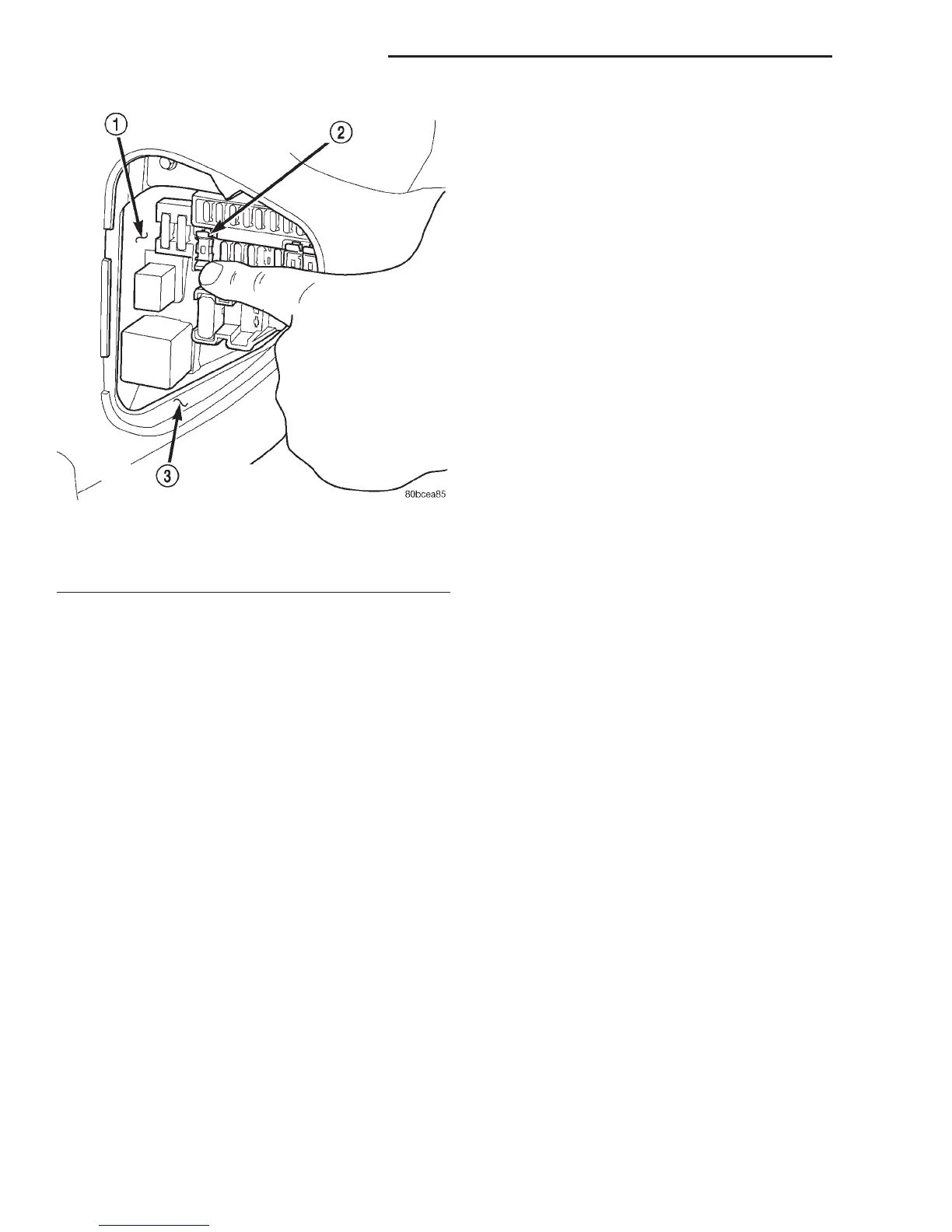
Fig. 10 Ignition-Off Draw Fuse - Typical
1 – JUNCTION BLOCK
2 – IGNITION-OFF DRAW FUSE AND HOLDER
3 – LEFT INSTRUMENT PANEL END BRACKET
8O - 8 POWER DISTRIBUTION SYSTEMS DN
REMOVAL AND INSTALLATION (Continued)