(1) Be certain that the ignition switch is in the Off
position, before you begin the demagnetizing proce-
dure.
(2) Connect the degaussing tool to an electrical
outlet, while keeping the tool at least 61 centimeters
(2 feet) away from the compass unit.
(3) Slowly approach the head of the overhead con-
sole forward mounting screw with the degaussing
tool connected.
(4) Contact the head of the screw with the plastic
coated tip of the degaussing tool for about two sec-
onds.
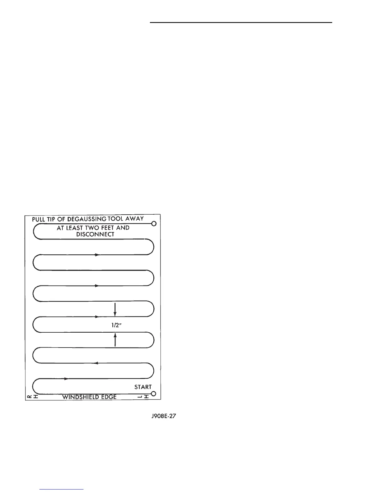
(5) With the degaussing tool still energized, slowly
back it away from the screw. When the tip of the tool
is at least 61 centimeters (2 feet) from the screw
head, disconnect the tool.
(6) Place a piece of paper approximately 22 by 28
centimeters (8.5 by 11 inches), oriented on the vehicle
lengthwise from front to rear, on the center line of
the roof at the windshield header (Fig. 3). The pur-
pose of the paper is to protect the roof panel from
scratches, and to define the area to be demagnetized.
(7) Connect the degaussing tool to an electrical
outlet, while keeping the tool at least 61 centimeters
(2 feet) away from the compass unit.
(8) Slowly approach the center line of the roof
panel at the windshield header, with the degaussing
tool connected.
(9) Contact the roof panel with the plastic coated
tip of the degaussing tool. Be sure that the template
is in place to avoid scratching the roof panel. Using a
slow, back-and-forth sweeping motion, and allowing
13 millimeters (0.50 inch) between passes, move the
tool at least 11 centimeters (4 inches) to each side of
the roof center line, and 28 centimeters (11 inches)
back from the windshield header.
(10) With the degaussing tool still energized,
slowly back it away from the roof panel. When the
tip of the tool is at least 61 centimeters (2 feet) from
the roof panel, disconnect the tool.
(11) Calibrate the compass and adjust the compass
variance. Refer to Compass Variation Adjustment
and Compass Calibration in the Service Proce-
dures section of this group for the procedures.
REMOVAL AND INSTALLATION
OVERHEAD CONSOLE READING AND
COURTESY LAMP LENS
REMOVAL
(1) Disconnect and isolate the battery negative
cable.
(2) Insert a long, narrow, flat-bladed tool between
the edge of the reading and courtesy lamp lens and
the overhead console housing just inboard of the lens
pivots (Fig. 4).
(3) Gently pry downward against the reading and
courtesy lamp lens until the pivot of the lens is dis-
engaged from the pivot pin in the lens opening of the
overhead console housing.
(4) Repeat the procedure to disengage the second
lens pivot from its pivot pin.
(5) Pull the pivot end (inboard side) of the reading
and courtesy lamp lens horizontally inboard far
enough to disengage the switch actuator tab on the
outboard side of the lens from the overhead console
housing.
(6) Remove the reading and courtesy lamp lens
from the overhead console housing.
Fig. 3 Roof Demagnetizing Pattern
8V - 8 OVERHEAD CONSOLE SYSTEMS DN
SERVICE PROCEDURES (Continued)