INSTALLATION
(1) Position the switch actuator tab on the out-
board side of the reading and courtesy lamp lens into
the lens opening of the overhead console housing.
The lens actuator tab should be positioned directly
over the switch plunger, which is located just out-
board of the lens opening.
(2) Align the two pivots on the inboard side of the
reading and courtesy lamp lens with the two pivot
pins on the inboard end of the lens opening in the
overhead console housing.
(3) Push firmly and evenly upward on the reading
and courtesy lamp lens directly over each of the two
pivots until they snap into place over the pivot pins
in the lens opening of the overhead console housing.
(4) Reconnect the battery negative cable.
OVERHEAD CONSOLE
REMOVAL
OVERHEAD CONSOLE
(1) Disconnect and isolate the battery negative
cable.
(2) Remove the screw that secures the front of the
overhead console to the front of the overhead console
bracket (Fig. 5).
(3) Insert the fingertips of both hands between the
headliner and the sides of the overhead console hous-
ing in the area between the garage door opener stor-
age bin and the sunglasses storage bin.
(4) Pull downward on the sides of the overhead
console housing firmly and evenly to disengage the
two snap clips that secure the rear of the unit from
their receptacles in the overhead console bracket.
(5) Lower the overhead console from the headliner
far enough to access the wire harness connector.
(6) Disconnect the roof wire harness connector
from the overhead console wire harness connector.
(7) Remove the overhead console from the head-
liner.
OVERHEAD CONSOLE BRACKET
(1) Disconnect and isolate the battery negative
cable.
(2) Remove the overhead console from the over-
head console bracket. Refer to Overhead Console in
the Removal and Installation section of this group for
the procedures.
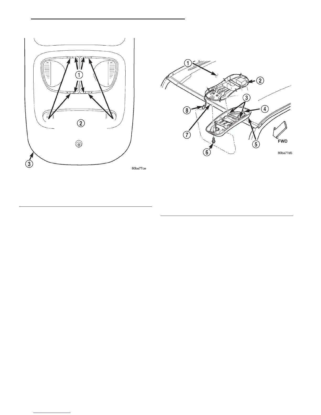
Fig. 4 Overhead Console Reading and Courtesy
Lamp Lens Remove/Install
1 – PRY HERE
2 – READING AND COURTESY LAMP LENS PIVOTS
3 – OVERHEAD CONSOLE
Fig. 5 Overhead Console Remove/Install
1 – HEADLINER
2 – BRACKET
3 – SNAP CLIP (2)
4 – LOCATING PIN
5 – OVERHEAD CONSOLE
6 – SCREW
7 – FRONT HEADER
8 – ROOF WIRE HARNESS CONNECTOR
DN OVERHEAD CONSOLE SYSTEMS 8V - 9
REMOVAL AND INSTALLATION (Continued)