(5) Disengage the overhead console wire harness
connector from the mount on the paperclip by push-
ing the connector firmly toward the left side of the
overhead console housing.
(6) Remove the paperclip from the overhead con-
sole housing.
INSTALLATION
(1) Position the paperclip onto the overhead con-
sole housing.
(2) Engage the overhead console wire harness con-
nector onto the mount on the paperclip by aligning
the channels on the connector with the tab on the
mount and pushing the connector firmly toward the
right side of the overhead console housing.
(3) Install and tighten the four screws that secure
the paperclip to the overhead console housing.
Tighten the screws to 2.2 N·m (20 in. lbs.).
(4) Install the overhead console onto the headliner.
Refer to Overhead Console in the Removal and
Installation section of this group for the procedures.
(5) Reconnect the battery negative cable.
COMPASS MINI-TRIP COMPUTER
REMOVAL
(1) Disconnect and isolate the battery negative
cable.
(2) Remove the overhead console from the head-
liner. Refer to Overhead Console in the Removal
and Installation section of this group for the proce-
dures.
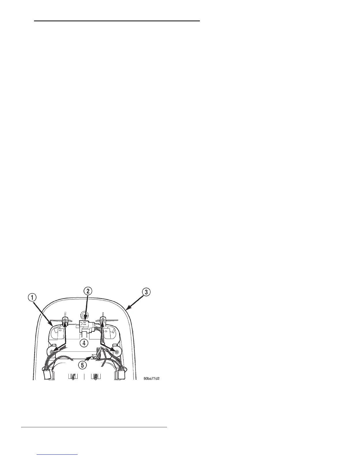
(3) Remove the four screws that secure the com-
pass mini-trip computer module to the overhead con-
sole housing (Fig. 7).
(4) Pull the compass mini-trip computer module
away from the overhead console far enough to access
the wire harness connectors.
(5) Disengage the overhead console wire harness
connector from the mount on the compass mini-trip
computer module housing by pushing the connector
firmly toward the left side of the overhead console
housing.
(6) Disconnect the overhead console wire harness
connector from the compass mini-trip computer mod-
ule connector receptacle.
(7) Remove the compass mini-trip computer mod-
ule from the overhead console housing.
INSTALLATION
(1) Position the compass mini-trip computer mod-
ule onto the overhead console housing.
(2) Reconnect the overhead console wire harness
connector to the compass mini-trip computer module
connector receptacle.
(3) Engage the overhead console wire harness con-
nector onto the mount on the compass mini-trip com-
puter module housing by aligning the channels on
the connector with the tab on the mount and pushing
the connector firmly toward the right side of the
overhead console housing.
(4) Install and tighten the four screws that secure
the compass mini-trip computer module to the over-
head console housing. Tighten the screws to 2.2 N·m
(20 in. lbs.).
(5) Install the overhead console onto the headliner.
Refer to Overhead Console in the Removal and
Installation section of this group for the procedures.
(6) Reconnect the battery negative cable.
NOTE: If a new compass mini-trip computer has
been installed, the compass will have to be cali-
brated and the variance set. Refer to Compass Vari-
ation Adjustment and Compass Calibration in the
Service Procedures section of this group for the
procedures.
OVERHEAD CONSOLE READING AND
COURTESY LAMP HOUSING
REMOVAL
(1) Disconnect and isolate the battery negative
cable.
(2) Remove the compass mini-trip computer mod-
ule from the overhead console housing. Refer to
Compass Mini-Trip Computer in the Removal and
Installation section of this group for the procedures.
Fig. 7 Compass Mini-Trip Computer Remove/Install
1 – COMPASS MINI-TRIP COMPUTER MODULE
2 – OVERHEAD CONSOLE WIRE HARNESS CONNECTOR
3 – OVERHEAD CONSOLE HOUSING
4 – SCREW (4)
5 – COMPUTER CONNECTOR
DN OVERHEAD CONSOLE SYSTEMS 8V - 11
REMOVAL AND INSTALLATION (Continued)