firing order is 1–8–4–3–6–5–7–2. The engine serial
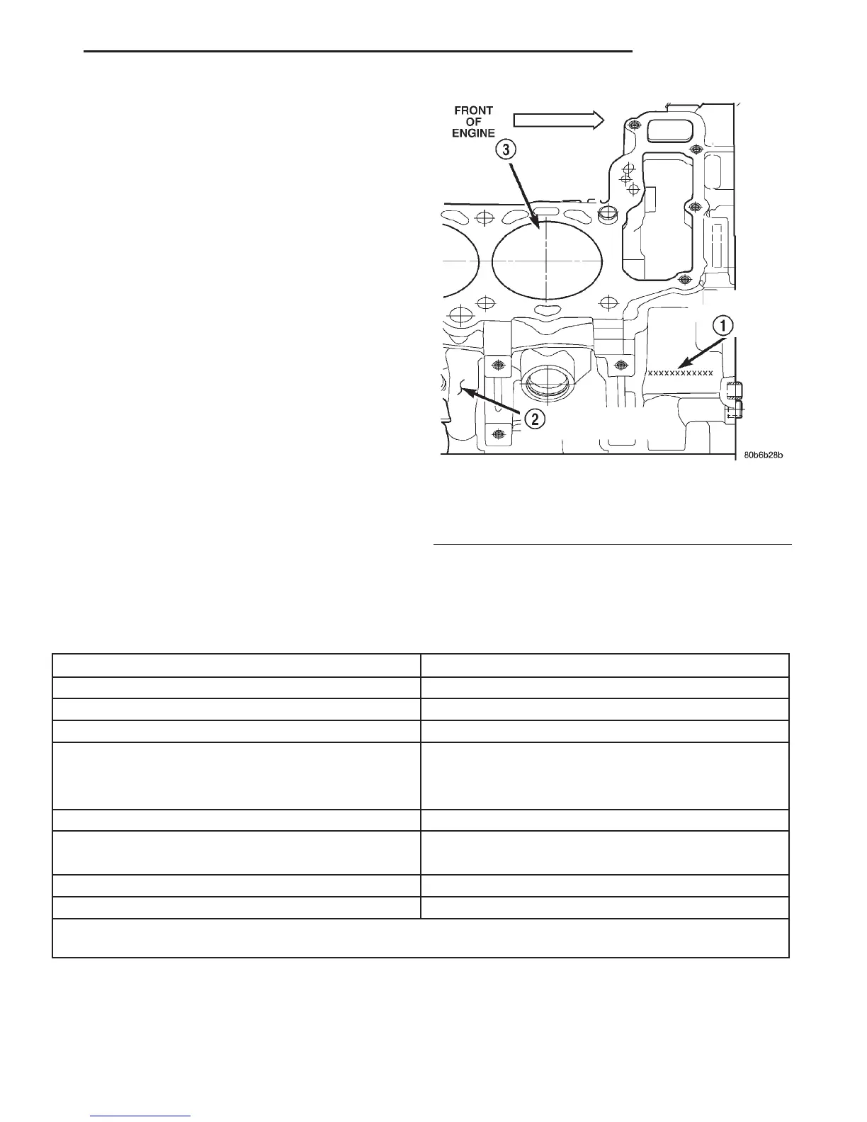
number is located at the right front side of the
engine block (Fig. 1)
ENGINE LUBRICATION SYSTEM
DESCRIPTION
The lubrication system (Fig. 2) is a full flow filtra-
tion pressure feed type.
OPERATION
Oil from the oil pan is pumped by a gerotor type oil
pump directly mounted to the crankshaft nose. Oil
pressure is controlled by a relief valve mounted
inside the oil pump housing. For lubrication flow
refer to (Fig. 2).
The camshaft exhaust valve lobes and rocker arms
are lubricated through a small hole in the rocker
arm; oil flows through the lash adjuster then through
the rocker arm and onto the camshaft lobe. Due to
the orentation of the rocker arm, the camshaft intake
lobes are not lubed in the same manner as the
exhaust lobes. The intake lobes are lubed through
internal passages in the camshaft. Oil flows through
a bore in the number 3 camshaft bearing bore, and
as the camshaft turns, a hole in the camshaft aligns
with the hole in the camshaft bore allowing engine
oil to enter the camshaft tube. The oil then exits
through 1.6mm (0.063 in.) holes drilled into the
intake lobes, lubricating the lobes and the rocker
arms.
ENGINE LUBRICATION FLOW CHART—BLOCK: TABLE 1
FROM TO
Oil Pickup Tube Oil Pump
Oil Pump Oil Filter
Oil Filter Block Main Oil Gallery
Block Main Oil Gallery 1. Crankshaft Main Journal
2. Left Cylinder Head*
3. Right Cylinder Head*
Crankshaft Main Journals Crankshaft Rod Journals
Crankshaft Number One Main Journal 1.Front Timing Chain Idler Shaft
2. Both Secondary Chain Tensioners
Left Cylinder Head See Table 2
Right Cylinder Head See Table 2
* The cylinder head
gaskets have an oil restricter to control oil flow to the cylinder heads.
Fig. 1 Engine Identification Location.
1 – VEHICLE VIN NUMBER LOCATION
2 – CYLINDER BLOCK RIGHT HAND SIDE
3 – CYLINDER BORE #2
DN 4.7L ENGINE 9 - 3
DESCRIPTION AND OPERATION (Continued)