ring gap should be between 0.508-0.762 mm (0.020-
0.030 inch). The oil ring gap should be 0.254-1.270
mm (0.010-0.050 inch).
(c) Rings with insufficient end gap may be prop-
erly filed to the correct dimension. Rings with
excess gaps should not be used.
(2) Install rings and confirm ring side clearance:
(a) Install oil rings being careful not to nick or
scratch the piston. Install the oil control rings
according to instructions in the package. It is not
necessary to use a tool to install the upper and
lower rails. Insert oil rail spacer first, then side
rails.
(b) Install the second compression rings using
Installation Tool C-4184. The compression rings
must be installed with the identification mark face
up (toward top of piston) and chamfer facing down.
An identification mark on the ring is a drill point,
a stamped letter “O”, an oval depression or the
word TOP (Fig. 26) (Fig. 28).
(c) Using a ring installer, install the top com-
pression ring with the chamfer facing up (Fig. 27)
(Fig. 28). An identification mark on the ring is a
drill point, a stamped letter “O”, an oval depression
or the word TOP facing up.
(d) Measure side clearance between piston ring
and ring land. Clearance should be 0.074-0.097 mm
(0.0029-0.0038 inch) for the compression rings. The
steel rail oil ring should be free in groove, but
should not exceed 0.246 mm (0.0097 inch) side
clearance.
(e) Pistons with insufficient or excessive side
clearance should be replaced.
PISTON MEASUREMENT CHART
PISTON A DIA = PISTON BORE
SIZE DIAMETER DIAMETER
MIN. MAX. MIN. MAX.
mm
(in.)
mm
(in.)
mm
(in.)
mm (in.)
A ————
B 101.580 101.592 101.605 101.618
(3.9992) (3.9997) (4.0002) (4.0007)
C 101.592 101.605 101.618 101.630
(3.9997) (4.0002) (4.0007) (4.0012)
D 101.605 101.618 101.630 101.643
(4.0002) (4.0007) (4.0012) (4.0017)
E ————
DESCRIPTION SPECIFICATION
PISTON PIN BORE 25.007 - 25.015 mm
(.9845 -.9848 in.)
RING GROOVE
HEIGHT
OIL RAIL 4.033 - 4.058 mm
(.1588 -.1598 in.)
COMPRESSION
RAIL
1.529 - 1.554 mm
(.0602 -.0612 in.)
TOTAL FINISHED 470.8 6 2 grams
WEIGHT (16.607 6.0706 ounces)
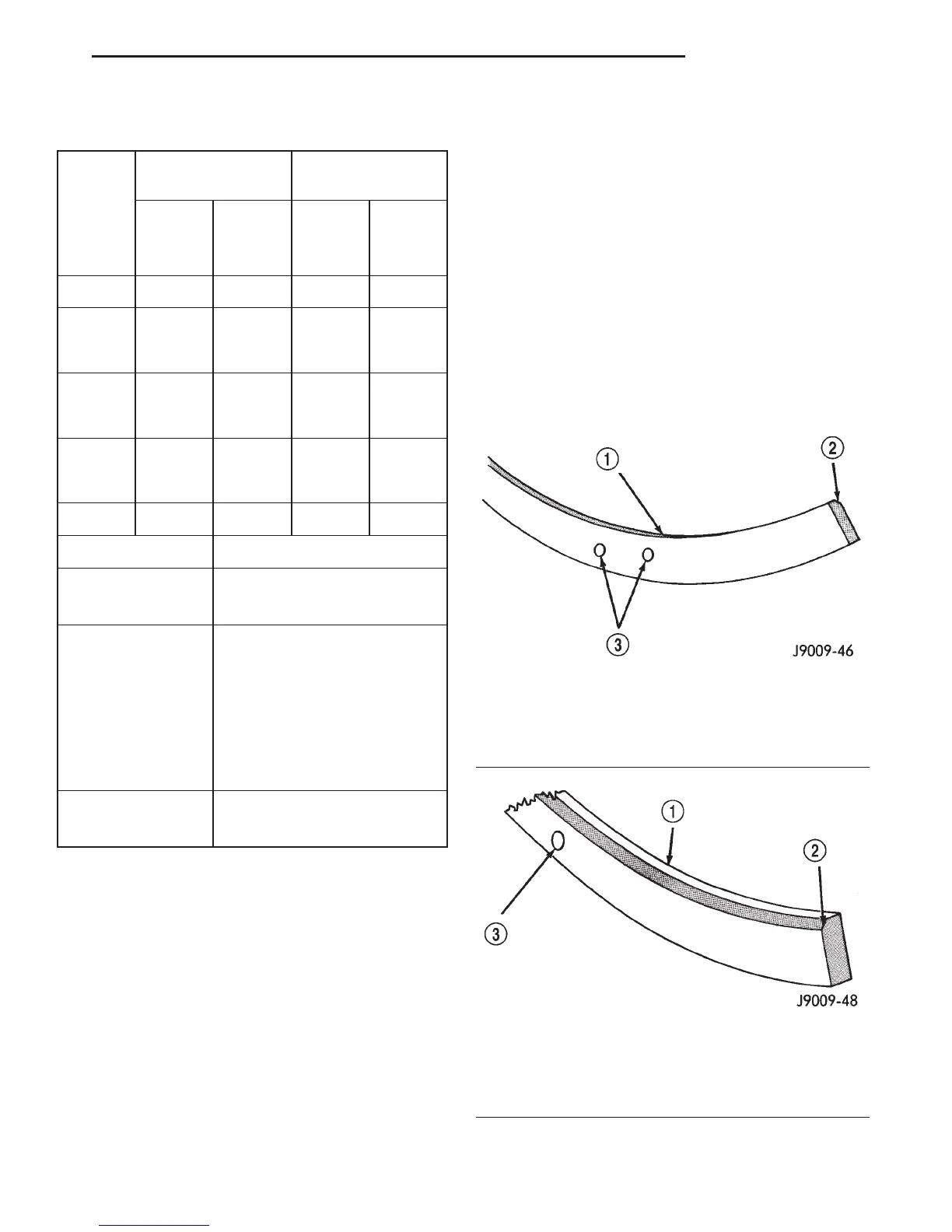
Fig. 26 Second Compression Ring Identification
(Typical)
1 – SECOND COMPRESSION RING (BLACK CAST IRON)
2 – CHAMFER
3 – TWO DOTS
Fig. 27 Top Compression Ring Identification
(Typical)
1 – TOP COMPRESSION RING (GRAY IN COLOR)
2 – CHAMFER
3 – ONE DOT
DN 5.2L ENGINE 9 - 99
SERVICE PROCEDURES (Continued)