CONNECTING ROD BEARINGS—FITTING
Fit all rods on a bank until completed. DO NOT
alternate from one bank to another, because connect-
ing rods and pistons are not interchangeable from
one bank to another.
The bearing caps are not interchangeable and
should be marked at removal to ensure correct
assembly.
Each bearing cap has a small V-groove across the
parting face. When installing the lower bearing shell,
make certain that the V-groove in the shell is in line
with the V-groove in the cap. This provides lubrica-
tion of the cylinder wall in the opposite bank.
The bearing shells must be installed so that the
tangs are in the machined grooves in the rods and
caps.
Limits of taper or out-of-round on any crankshaft
journals should be held to 0.025 mm (0.001 inch).
Bearings are available in 0.025 mm (0.001 inch),
0.051 mm (0.002 inch), 0.076 mm (0.003 inch), 0.254
mm (0.010 inch) and 0.305 mm (0.012 inch) under-
size. Install the bearings in pairs. DO NOT use a
new bearing half with an old bearing half. DO
NOT file the rods or bearing caps.
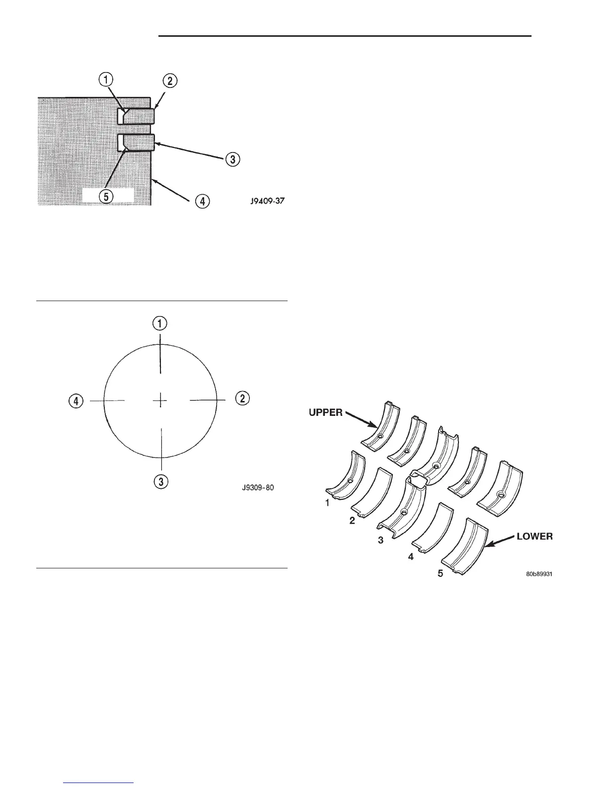
CRANKSHAFT MAIN BEARINGS—FITTING
Bearing caps are not interchangeable and should
be marked at removal to ensure correct assembly.
Upper and lower bearing halves are NOT inter-
changeable. Lower main bearing halves of No.2 and 4
are interchangeable.
Upper and lower No.3 bearing halves are flanged
to carry the crankshaft thrust loads. They are NOT
interchangeable with any other bearing halves in the
engine (Fig. 30). Bearing shells are available in stan-
dard and the following undersizes: 0.25 mm (0.001
inch), 0.051 mm (0.002 inch), 0.076 mm (0.003 inch),
0.254 mm (0.010 inch) and 0.305 mm (0.012 inch).
Never install an undersize bearing that will reduce
clearance below specifications.
REMOVAL AND INSTALLATION
ENGINE MOUNTS—FRONT
REMOVAL
On 4WD vehicles the engine front support brackets
attach directly to engine block and the axle housing.
The brackets provide a solid interconnection for these
units (Fig. 31) (Fig. 32). Engine must be supported
during any service procedures involving the front
support assemblies.
Fig. 28 Compression Ring Chamfer Location
(Typical)
1 – CHAMFER
2 – TOP COMPRESSION RING
3 – SECOND COMPRESSION RING
4 – PISTON
5 – CHAMFER
Fig. 29 Proper Ring Installation
1 – OIL RING SPACER GAP
2 – SECOND COMPRESSION RING GAP OIL RING RAIL GAP
(TOP)
3 – OIL RING RAIL GAP (BOTTOM)
4 – TOP COMPRESSION RING GAP
Fig. 30 Main Bearing Identification
9 - 100 5.2L ENGINE DN
SERVICE PROCEDURES (Continued)