place, inspect to make sure seals are in place.
Remove alignment studs if used.
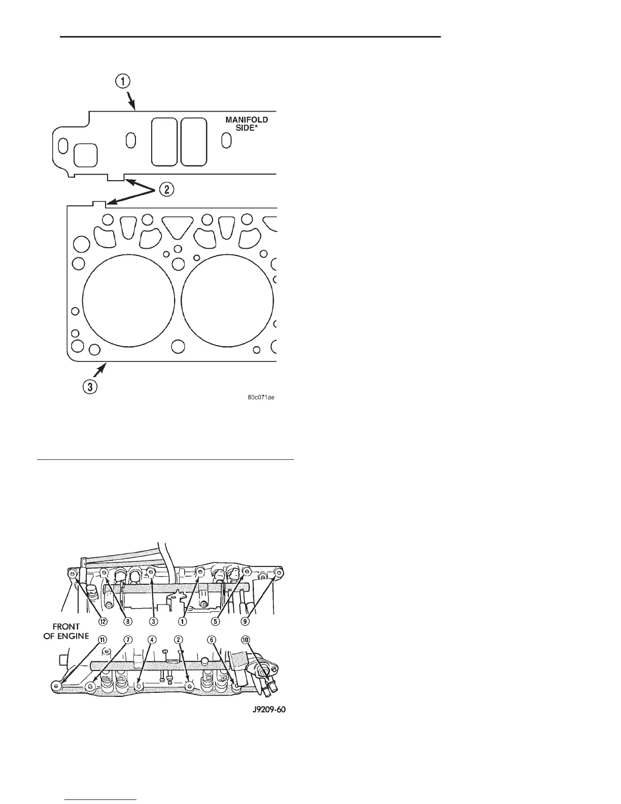
(9) The following torque sequence duplicates the
expected results of the automated assembly system
(Fig. 39).
• Step 1—Tighten bolts 1 thru 4, in sequence, to 8
N·m (72 in. lbs.) torque. Tighten in alternating steps
1.4 N·m (12 in. lbs.) torque at a time.
• Step 2—Tighten bolts 5 thru 12, in sequence, to
8 N·m (72 in. lbs.) torque.
• Step 3—Check that all bolts are tightened to 8
N·m (72 in. lbs.) torque.
• Step 4—Tighten all bolts, in sequence, to 16 N·m
(12 ft. lbs.) torque.
• Step 5—Check that all bolts are tightened to 16
N·m (12 ft. lbs.) torque.
(10) Install closed crankcase ventilation and evap-
oration control systems.
(11) Install the coil wires.
(12) Connect the coolant temperature sending unit
wire.
(13) Connect the heater hoses and bypass hose.
(14) Install distributor cap and wires.
(15) Connect the accelerator linkage and, if so
equipped, the speed control and transmission kick-
down cables.
(16) Install the fuel supply line to the fuel rail.
(17) Install the accessory drive bracket and A/C
compressor.
(18) Install the generator and accessory drive belt.
Tighten generator mounting bolt to 41 N·m (30 ft.
lbs.) torque.
(19) Install the air cleaner assembly and air inlet
hose.
(20) Fill cooling system.
(21) Connect the battery negative cable.
EXHAUST MANIFOLD
REMOVAL
(1) Disconnect the battery negative cable.
(2) Raise the vehicle.
(3) Remove the exhaust pipe to manifold nuts.
(4) Lower the vehicle.
(5) Remove three nuts, heat shield and washers
from the right side exhaust manifold, if necessary
(Fig. 40).
(6) Remove two nuts, heat shield and washers
from the left side exhaust manifold, if necessary (Fig.
41).
(7) Remove bolts, nuts and washers attaching
manifold to cylinder head.
(8) Remove manifold from the cylinder head.
INSTALLATION
CAUTION: If the studs came out with the nuts when
removing the exhaust manifold, install new studs.
(1) Position the exhaust manifolds on the two
studs located on the cylinder head. Install conical
washers and nuts on these studs (Fig. 42).
Fig. 38 Intake Manifold Flange Gasket Alignment
1 – FLANGE GASKET
2 – ALIGNMENT TABS
3 – CYLINDER HEAD GASKET
Fig. 39 Intake Manifold Bolt Tightening Sequence—
5.9L Engine
DN 5.2L ENGINE 9 - 105
REMOVAL AND INSTALLATION (Continued)