(2) Install new bolt and washer assemblies in the
remaining holes (Fig. 42). Start at the center arm
and work outward. Tighten the bolts and nuts to 24
N·m (18 ft. lbs.) torque.
(3) Position three washers, heat shield and nuts on
the right side exhaust manifold. Tighten nuts to 24
N·m (18 ft. lbs.).
(4) Position two washers, heat shield and nuts on
the left side exhaust manifold. Tighten nuts to 24
N·m (18 ft. lbs.).
(5) Raise the vehicle.
(6) Assemble the exhaust pipe to the exhaust man-
ifold and secure with bolts, nuts and washers.
Tighten these nuts to 27 N·m (20 ft. lbs.) torque.
(7) Lower the vehicle.
(8) Connect the battery negative cable.
CYLINDER HEAD COVER
A steel backed silicon gasket is used with the cyl-
inder head cover (Fig. 43). This gasket can be used
again.
REMOVAL
(1) Disconnect the negative cable from the battery.
(2) Disconnect closed ventilation system and evap-
oration control system from cylinder head cover.
(3) Remove the air inlet hose.
(4) Remove cylinder head cover and gasket. The
gasket may be used again.
INSTALLATION
(1) The cylinder head cover gasket can be used
again. Install the gasket onto the head rail.
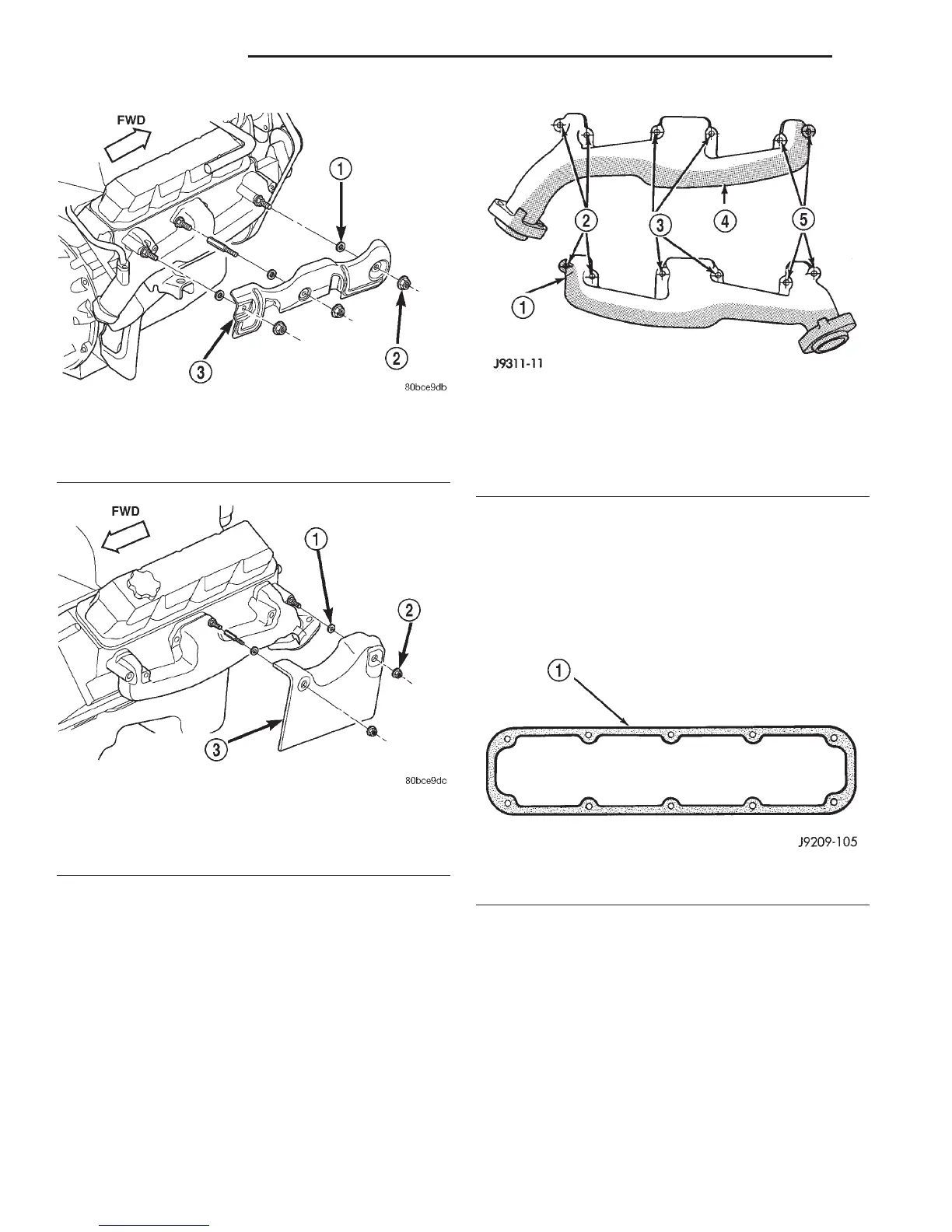
Fig. 40 Exhaust Manifold Heat Shield—Right Side
1 – WASHER
2 – NUT AND WASHER
3 – EXHAUST MANIFOLD HEAT SHIELD
Fig. 41 Exhaust Manifold Heat Shield—Left Side
1 – WASHER
2 – NUT AND WASHER
3 – EXHAUST MANIFOLD HEAT SHIELD
Fig. 42 Exhaust Manifold Installation—5.9L Engine
1 – EXHAUST MANIFOLD (LEFT)
2 – BOLTS & WASHERS
3 – NUTS & WASHERS
4 – EXHAUST MANIFOLD (RIGHT)
5 – BOLTS & WASHERS
Fig. 43 Cylinder Head Cover Gasket
1 – CYLINDER HEAD COVER GASKET
9 - 106 5.2L ENGINE DN
REMOVAL AND INSTALLATION (Continued)