(6) To align the bearing cap, use cap slot, align-
ment dowel and cap bolts. DO NOT remove excess
material after assembly. DO NOT strike rear cap
more than 2 times for proper engagement.
(7) Install the rear main bearing cap with cleaned
and oiled cap bolts. Alternately tighten ALL cap bolts
to 115 N·m (85 ft. lbs.) torque.
(8) Install oil pump.
(9) Apply Mopart Silicone Rubber Adhesive Seal-
ant, or equivalent, at bearing cap to block joint to
provide cap to block and oil pan sealing (Fig. 72).
Apply enough sealant until a small amount is
squeezed out. Withdraw nozzle and wipe excess seal-
ant off the oil pan seal groove.
(10) Immediately install the oil pan.
LOWER SEAL
REMOVAL
(1) Remove the oil pan.
(2) Remove the oil pump from the rear main bear-
ing cap.
(3) Remove the rear main bearing cap and discard
the old lower seal.
INSTALLATION
(1) Clean the rear main cap mating surfaces
including the oil pan gasket groove.
(2) Carefully install a new upper seal (refer to
Upper Seal Replacement - Crankshaft Installed pro-
cedure above).
(3) Lightly oil the new lower seal lips with engine
oil.
(4) Install a new lower seal in bearing cap with
the white paint facing the rear of engine.
(5) Apply 5 mm (0.20 in) drop of Mopart Gasket
Maker, or equivalent, on each side of the rear main
bearing cap (Fig. 71). DO NOT over apply sealant or
allow the sealant to contact the rubber seal. Assem-
ble bearing cap to cylinder block immediately after
sealant application.
(6) To align the bearing cap, use cap slot, align-
ment dowel and cap bolts. DO NOT remove excess
material after assembly. DO NOT strike rear cap
more than 2 times for proper engagement.
(7) Install the rear main bearing cap with cleaned
and oiled cap bolts. Alternately tighten the cap bolts
to 115 N·m (85 ft. lbs.) torque.
(8) Install oil pump.
(9) Apply Mopart Silicone Rubber Adhesive Seal-
ant, or equivalent, at bearing cap to block joint to
provide cap to block and oil pan sealing (Fig. 72).
Apply enough sealant until a small amount is
squeezed out. Withdraw nozzle and wipe excess seal-
ant off the oil pan seal groove.
(10) Immediately install the oil pan.
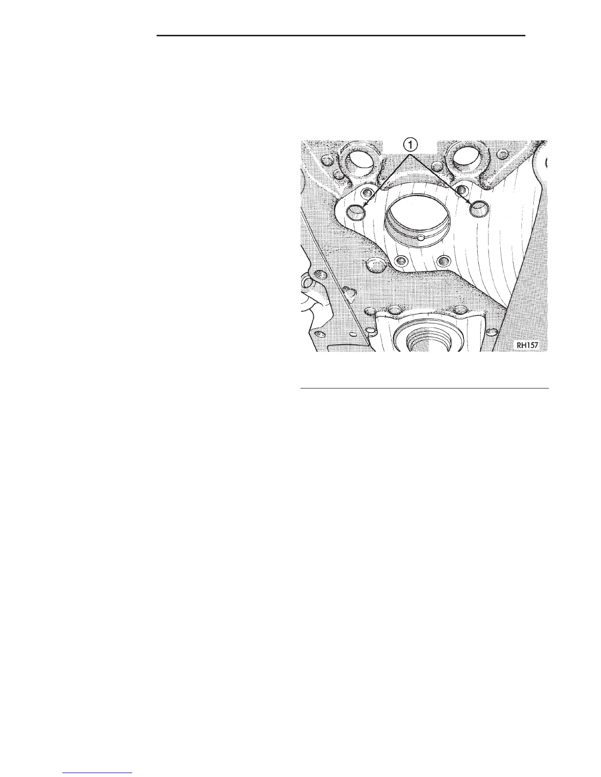
ENGINE CORE OIL AND CAMSHAFT PLUGS
Engine core plugs have been pressed into the oil
galleries behind the camshaft thrust plate (Fig. 73).
This will reduce internal leakage and help maintain
higher oil pressure at idle.
REMOVAL
(1) Using a blunt tool such as a drift or a screw-
driver and a hammer, strike the bottom edge of the
cup plug (Fig. 74).
(2) With the cup plug rotated, grasp firmly with
pliers or other suitable tool and remove plug (Fig.
74).
INSTALLATION
Thoroughly clean inside of cup plug hole in cylin-
der block or head. Be sure to remove old sealer.
Be certain the new plug is cleaned of all oil or
grease.
(1) Coat edges of plug and core hole with Mopart
Gasket Maker, or equivalent.
CAUTION: DO NOT drive cup plug into the casting,
as restricted coolant flow can result and cause seri-
ous engine problems.
(2) Using proper plug drive, drive cup plug into
hole. The sharp edge of the plug should be at least
0.50 mm (0.020 in.) inside the lead-in chamfer.
(3) It is not necessary to wait for curing of the
sealant. The cooling system can be filled and the
vehicle placed in service immediately.
Fig. 73 Location of Cup Plugs in Oil Galleries
1 – CUP PLUGS
9 - 120 5.2L ENGINE DN
REMOVAL AND INSTALLATION (Continued)