DISASSEMBLY AND ASSEMBLY
VALVE SERVICE
VALVE GUIDES
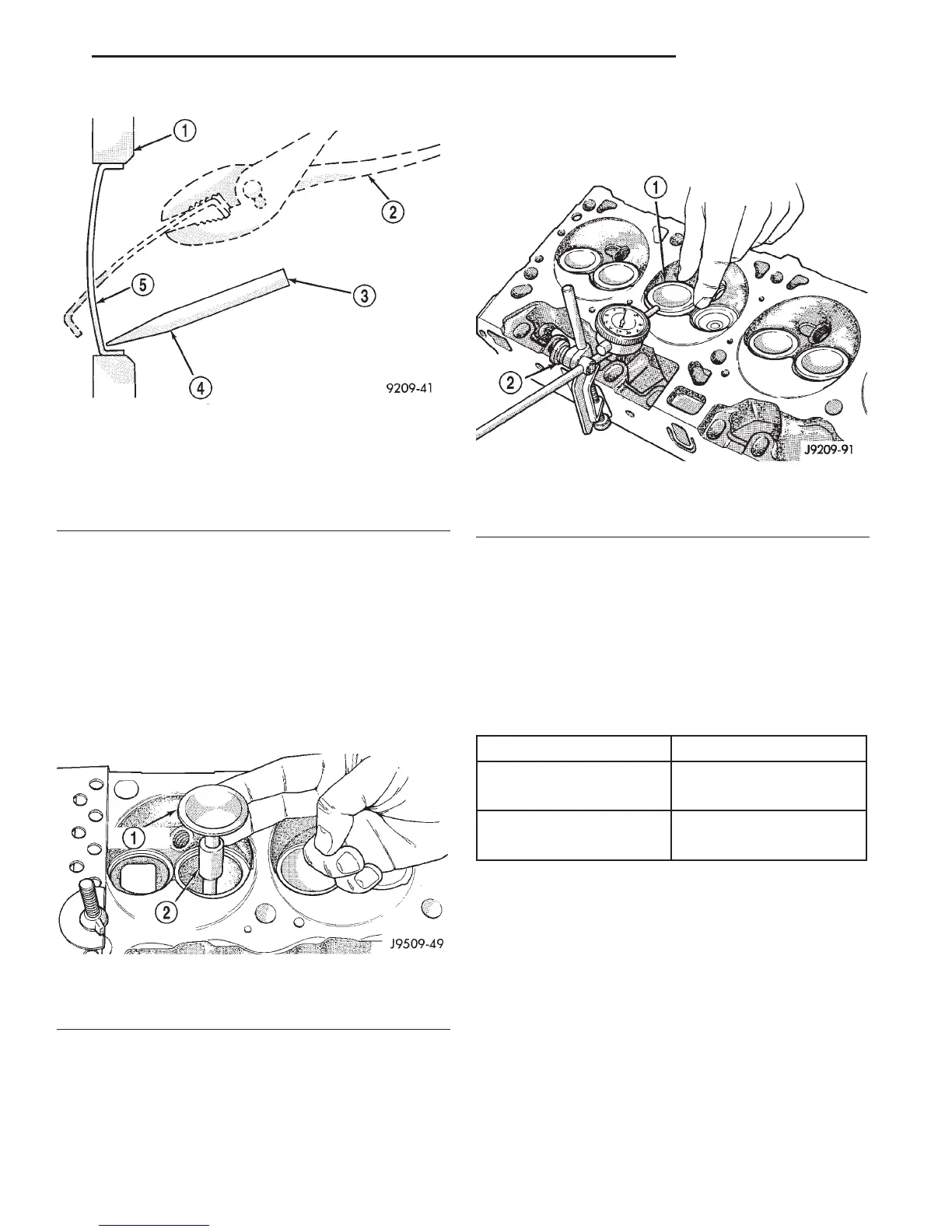
Measure valve stem guide clearance as follows:
(1) Install Valve Guide Sleeve Tool C-3973 over
valve stem and install valve (Fig. 75). The special
sleeve places the valve at the correct height for
checking with a dial indicator.
(2) Attach Dial Indicator Tool C-3339 to cylinder
head and set it at right angle of valve stem being
measured (Fig. 76).
(3) Move valve to and from the indicator. The total
dial indicator reading should not exceed 0.432 mm
(0.017 inch). Ream the guides for valves with over-
size stems if dial indicator reading is excessive or if
the stems are scuffed or scored.
(4) Service valves with oversize stems are avail-
able as shown below.
(5) Slowly turn reamer by hand and clean guide
thoroughly before installing new valve. Ream the
valve guides from standard to 0.381 mm (0.015
inch). Use a 2 step procedure so the valve
guides are reamed true in relation to the valve
seat:
• Step 1—Ream to 0.0763 mm (0.003 inch).
• Step 2—Ream to 0.381 mm (0.015 inch).
Fig. 74 Core Hole Plug Removal
1 – CYLINDER BLOCK
2 – REMOVE PLUG WITH PLIERS
3 – STRIKE HERE WITH HAMMER
4 – DRIFT PUNCH
5 – CUP PLUG
Fig. 75 Positioning Valve with Tool C-3973
1 – VALVE
2 – SPACER TOOL
Fig. 76 Measuring Valve Guide Wear
1 – VALVE
2 – SPECIAL TOOL C-3339
REAMER SIZES CHART
REAMER O/S VALVE GUIDE SIZE
0.076 mm 8.026 - 8.052 mm
(0.003 in.) (0.316 - 0.317 in.)
0.381 mm 8.331 - 8.357 mm
(0.015 in.) (0.328 - 0.329 in.)
DN 5.2L ENGINE 9 - 121
REMOVAL AND INSTALLATION (Continued)