REFACING VALVES AND VALVE SEATS
The intake and exhaust valves have a 43-1/4° to
43-3/4° face angle and a 44-1/4° to 44-3/4° seat angle
(Fig. 77).
VALVES
Inspect the remaining margin after the valves are
refaced (Fig. 78). Valves with less than 1.190 mm
(0.047 inch) margin should be discarded.
VALVE SEATS
CAUTION: DO NOT un-shroud valves during valve
seat refacing (Fig. 79).
(1) When refacing valve seats, it is important that
the correct size valve guide pilot be used for reseat-
ing stones. A true and complete surface must be
obtained.
Fig. 77 Valve Face and Seat Angles
1 – CONTACT POINT
ITEM DESCRIPTION SPECIFICATION
A SEAT WIDTH - 1.016 - 1.524
mm
INTAKE (0.040 - 0.060
in.)
EXHAUST 1.524 - 2.032
mm
(0.060 - 0.080
in.)
B FACE ANGLE
(INT. AND
EXT.)
43
1
⁄
4
°-43
3
⁄
4
°
C SEAT ANGLE
(INT. AND
EXT.)
44
1
⁄
4
°-44
3
⁄
4
°
D CONTACT
SURFACE —
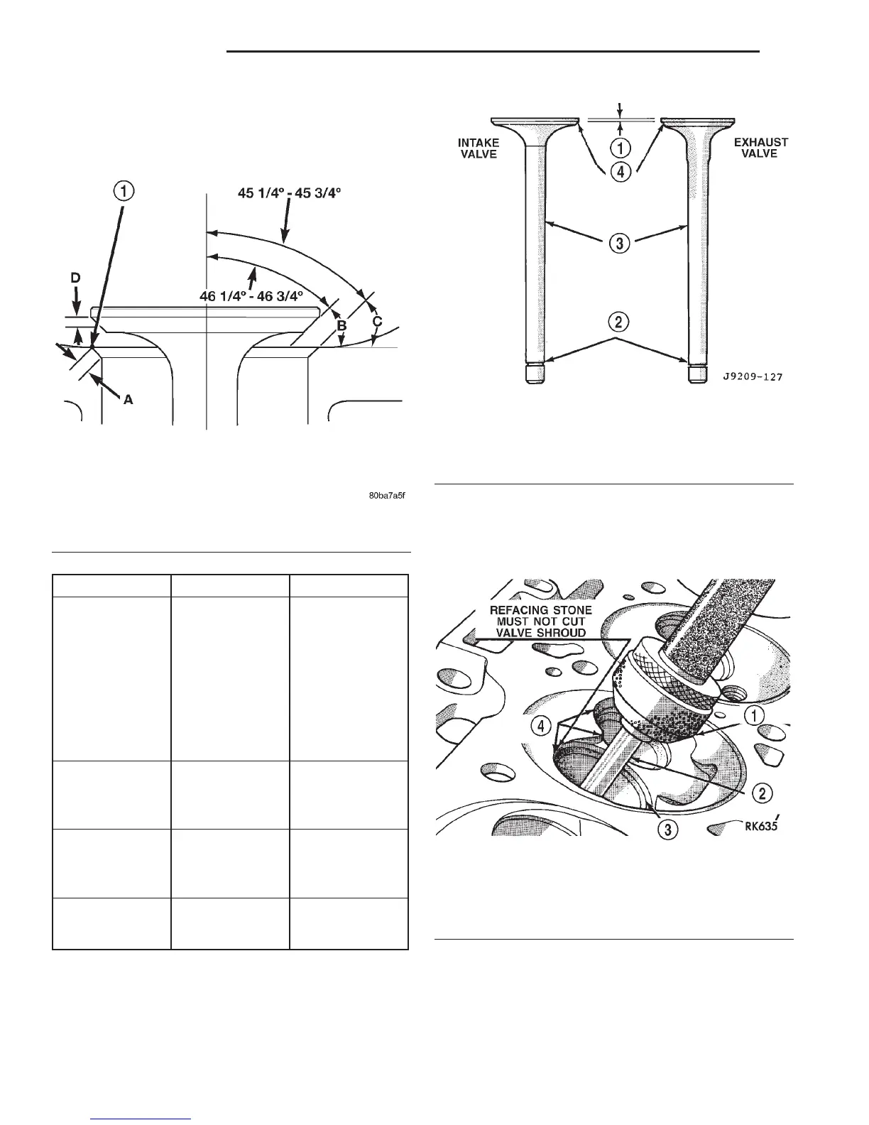
Fig. 78 Intake and Exhaust Valves
1 – MARGIN
2 – VALVE SPRING RETAINER LOCK GROOVE
3 – STEM
4–FACE
Fig. 79 Refacing Valve Seats
1–STONE
2 – PILOT
3 – VALVE SEAT
4 – SHROUD
9 - 122 5.2L ENGINE DN
DISASSEMBLY AND ASSEMBLY (Continued)