Clean oil pan in solvent and wipe dry with a clean
cloth.
Clean oil screen and pipe thoroughly in clean sol-
vent. Inspect condition of screen.
INSPECTION
Inspect oil drain plug and plug hole for stripped or
damaged threads. Repair as necessary.
Inspect oil pan mounting flange for bends or distor-
tion. Straighten flange, if necessary.
OIL PUMP
INSPECTION
Mating surface of the oil pump cover should be
smooth. Replace pump assembly if cover is scratched
or grooved.
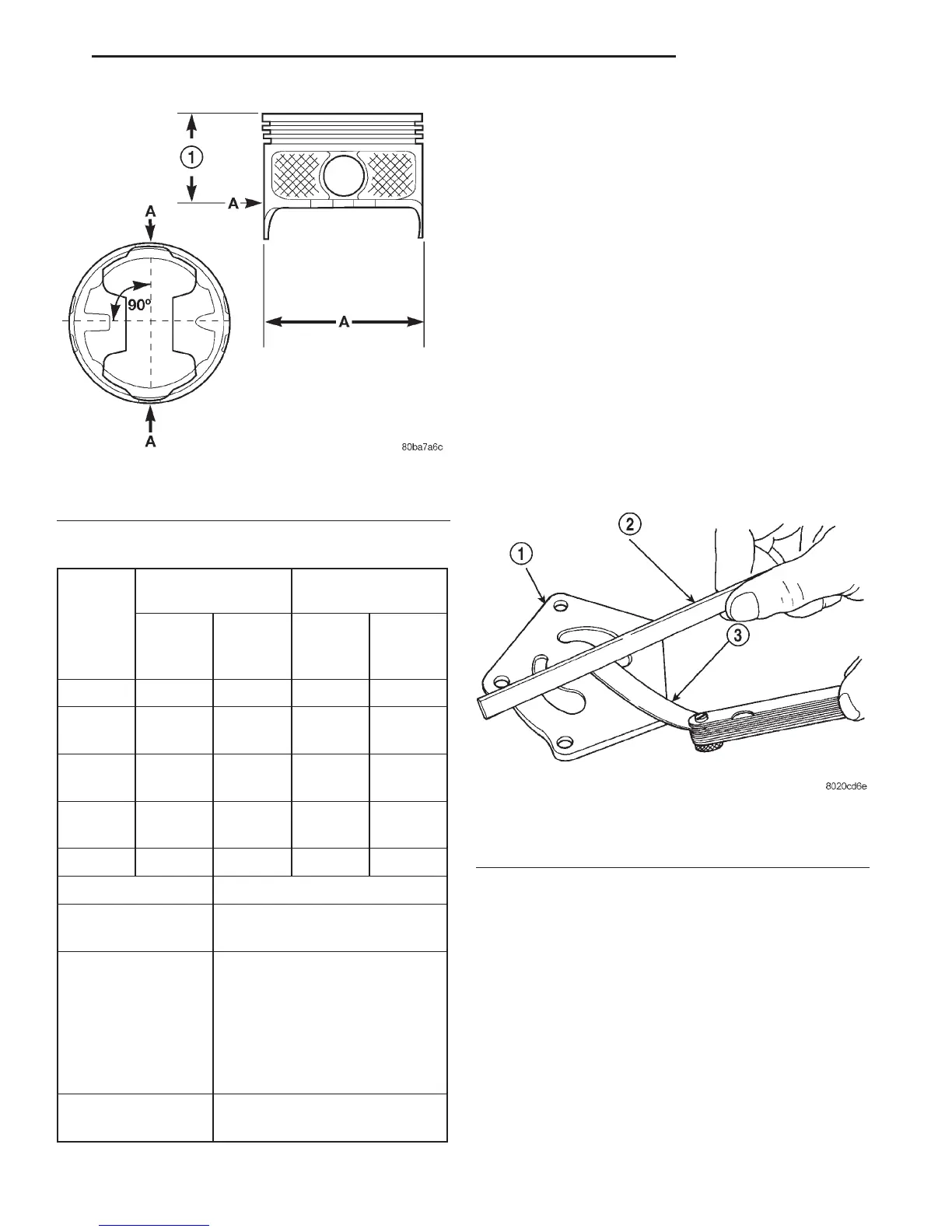
Lay a straightedge across the pump cover surface
(Fig. 84). If a 0.038 mm (0.0015 inch) feeler gauge
can be inserted between cover and straightedge,
pump assembly should be replaced.
Measure thickness and diameter of OUTER rotor.
If outer rotor thickness measures 20.9 mm (0.825
inch) or less or if the diameter is 62.7 mm (2.469
inches) or less, replace outer rotor (Fig. 85).
If inner rotor measures 20.9 mm (0.825 inch) or
less, replace inner rotor and shaft assembly (Fig. 86).
Slide outer rotor into pump body. Press rotor to the
side with your fingers and measure clearance
between rotor and pump body (Fig. 87). If clearance
is 0.356 mm (0.014 inch) or more, replace oil pump
assembly.
Install inner rotor and shaft into pump body. If
clearance between inner and outer rotors is 0.203
mm (0.008 inch) or more, replace shaft and both
rotors (Fig. 88).
Fig. 83 Piston Measurements
1 – 49.53 mm
(1.95 IN.)
PISTON MEASUREMENT CHART
PISTON A DIA = PISTON BORE
SIZE DIAMETER DIAMETER
MIN. MAX. MIN. MAX.
mm
(in.)
mm
(in.)
mm
(in.)
mm (in.)
A ————
B 101.580 101.592 101.605 101.618
(3.9992) (3.9997) (4.0002) (4.0007)
C 101.592 101.605 101.618 101.630
(3.9997) (4.0002) (4.0007) (4.0012)
D 101.605 101.618 101.630 101.643
(4.0002) (4.0007) (4.0012) (4.0017)
E ————
DESCRIPTION SPECIFICATION
PISTON PIN 25.007 - 25.015 mm
BORE (.9845 -.9848 in.)
RING GROOVE
HEIGHT
OIL RAIL 4.033 - 4.058 mm
(.1588 -.1598 in.)
COMPRESSION
RAIL
1.529 - 1.554 mm
(.0602 -.0612 in.)
TOTAL FINISHED 470.8 6 2 grams
WEIGHT (16.607 6.0706 ounces)
Fig. 84 Checking Oil Pump Cover Flatness
1 – COVER
2 – STRAIGHT EDGE
3 – FEELER GAUGE
DN 5.2L ENGINE 9 - 125
CLEANING AND INSPECTION (Continued)