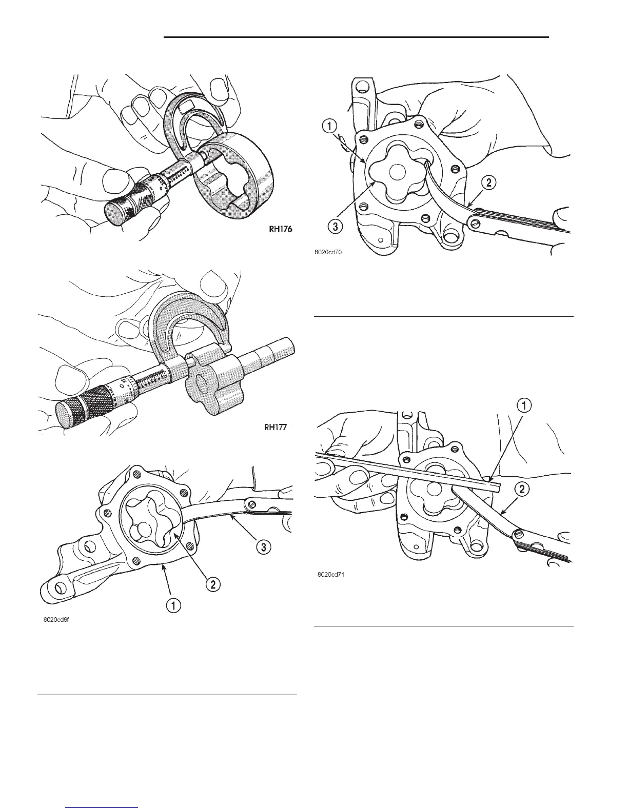
Place a straightedge across the face of the pump,
between bolt holes. If a feeler gauge of 0.102 mm
(0.004 inch) or more can be inserted between rotors
and the straightedge, replace pump assembly (Fig.
89).
Inspect oil pressure relief valve plunger for scoring
and free operation in its bore. Small marks may be
removed with 400-grit wet or dry sandpaper.
The relief valve spring has a free length of approx-
imately 49.5 mm (1.95 inches). The spring should
test between 19.5 and 20.5 pounds when compressed
to 34 mm (1-11/32 inches). Replace spring that fails
to meet these specifications (Fig. 90).
Fig. 85 Measuring Outer Rotor Thickness
Fig. 86 Measuring Inner Rotor Thickness
Fig. 87 Measuring Outer Rotor Clearance in
Housing
1 – PUMP BODY
2 – OUTER ROTOR
3 – FEELER GAUGE
Fig. 88 Measuring Clearance Between Rotors
1 – OUTER ROTOR
2 – FEELER GAUGE
3 – INNER ROTOR
Fig. 89 Measuring Clearance Over Rotors
1 – STRAIGHT EDGE
2 – FEELER GAUGE
9 - 126 5.2L ENGINE DN
CLEANING AND INSPECTION (Continued)