(7) Flip assembly and repeat Step 4, Step 5, and
Step 6 to remove the opposite bearing cap. This will
then allow removal of the cross centering kit assem-
bly and spring (Fig. 26).
(8) Press the remaining bearing caps out the other
end of the link yoke as described above to complete
the disassembly.
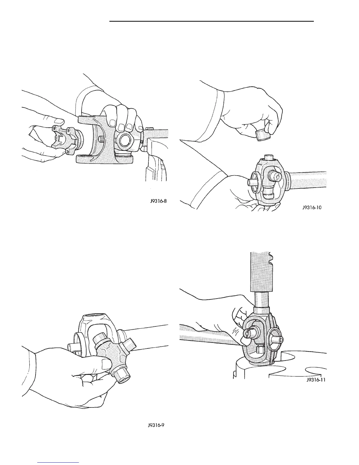
ASSEMBLY
During assembly, ensure that the alignment
marks on the link yoke and propeller shaft
yoke are aligned.
(1) Apply extreme pressure (EP) N.L.G.I. Grade 1
or 2 grease to inside of yoke bores to aid in installa-
tion.
(2) Fit a cross into the propeller shaft yoke (Fig.
27).
(3) Place a bearing cap over the trunnion and
align the cap with the yoke bore (Fig. 28). Keep the
needle bearings upright in the bearing assembly. A
needle bearing lying at the bottom of the cap will
prevent proper assembly.
(4) Press the bearing cap into the yoke bore
enough to install a snap ring (Fig. 29).
(5) Install a snap ring.
Fig. 26 Remove Centering Kit
Fig. 27 Install Cross In Yoke
Fig. 28 Install Bearing Cap
Fig. 29 Press In Bearing Cap
3 - 14 PROPELLER SHAFTS DN
DISASSEMBLY AND ASSEMBLY (Continued)