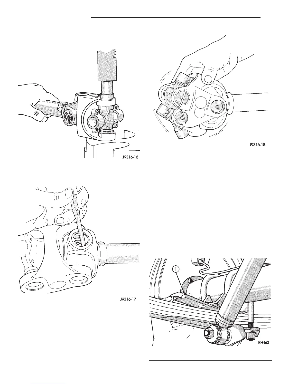
(11) Press the remaining two bearing caps into
place and install snap rings (Fig. 34).
(12) Tap the snap rings to allow them to seat into
the grooves (Fig. 35).
(13) Check for proper assembly. Flex the joint
beyond center, it should snap over-center in both
directions when correctly assembled (Fig. 36).
(14) Install the propeller shaft.
CLEANING AND INSPECTION
PROPELLER SHAFT
(1) Clean all universal joint bores with cleaning
solvent and a wire brush.
(2) Inspect the yokes for distortion, cracks, and
worn bearing cap bores.
ADJUSTMENTS
REAR AXLE PINION INPUT ANGLE
Adjust the rear axle pinion input angle on vehicles
equipped with leaf springs with tapered shims (Fig.
37). Install tapered shims between the springs and
axle pad to correct the angle. Refer to Group 2, Sus-
pension, for additional information.
Fig. 34 Press In Bearing Cap
Fig. 35 Seat Snap Rings In Groove
Fig. 36 Check Assembly
Fig. 37 Pinion Angle Adjustment at Leaf Springs
1 – WEDGE
3 - 16 PROPELLER SHAFTS DN
DISASSEMBLY AND ASSEMBLY (Continued)