INSTALLATION
(1) Align and connect the exhaust pipe/catalytic
converter to the muffler. Install exhaust clamp and
tighten clamp nuts to 42 N·m (31 ft. lbs.) torque.
(2) Connect the exhaust pipe(s) to the exhaust
manifold. Tighten the nuts to 34 N·m (25 ft. lbs.)
torque.
(3) Connect oxygen sensor connector(s).
(4) Lower the vehicle.
(5) Start the engine and inspect for exhaust leaks
and exhaust system contact with the body panels.
Adjust the alignment, if needed.
CATALYTIC CONVERTER
NOTE: Neither the inline catalytic converter nor the
mini catalytic converters (California emission vehi-
cles only) are serviceable separately from the
exhaust pipe. Refer to Exhaust Pipe for removal /
installation procedure.
MUFFLER
WARNING: IF TORCHES ARE USED WHEN WORK-
ING ON THE EXHAUST SYSTEM, WEAR PROTEC-
TIVE EYE COVERING AND DO NOT ALLOW THE
FLAME NEAR THE FUEL LINES.
CAUTION: When servicing or replacing exhaust
system components, be sure to disconnect all oxy-
gen sensor connectors. Allowing the exhaust sys-
tem to hang by the harness will damage the wiring
and/or sensor.
REMOVAL
(1) Disconnect battery negative cable.
(2) Raise vehicle on hoist.
(3) Remove muffler to exhaust pipe/catalytic con-
verter and tailpipe clamps (Fig. 10).
(4) Remove tailpipe from hanger isolator. Heat
muffler to tailpipe with an oxygen/acetylene torch
and twist tailpipe out of muffler.
(5) Disconnect muffler from hanger isolators (Fig.
10).
(6) Heat muffler to exhaust pipe/catalytic con-
verter connection and twist muffler off of converter
pipe.
INSTALLATION
(1) Install muffler to exhaust pipe/catalytic con-
verter and tailpipe. Install exhaust clamps and start
nuts by hand.
(2) Connect muffler to rear muffler hanger.
(3) Connect tailpipe to rear hanger.
(4) Align muffler and tighten exhaust clamp nuts
to 42 N·m (31 ft. lbs.).
(5) Lower vehicle and connect battery negative
cable.
(6) Start engine and check for exhaust leaks.
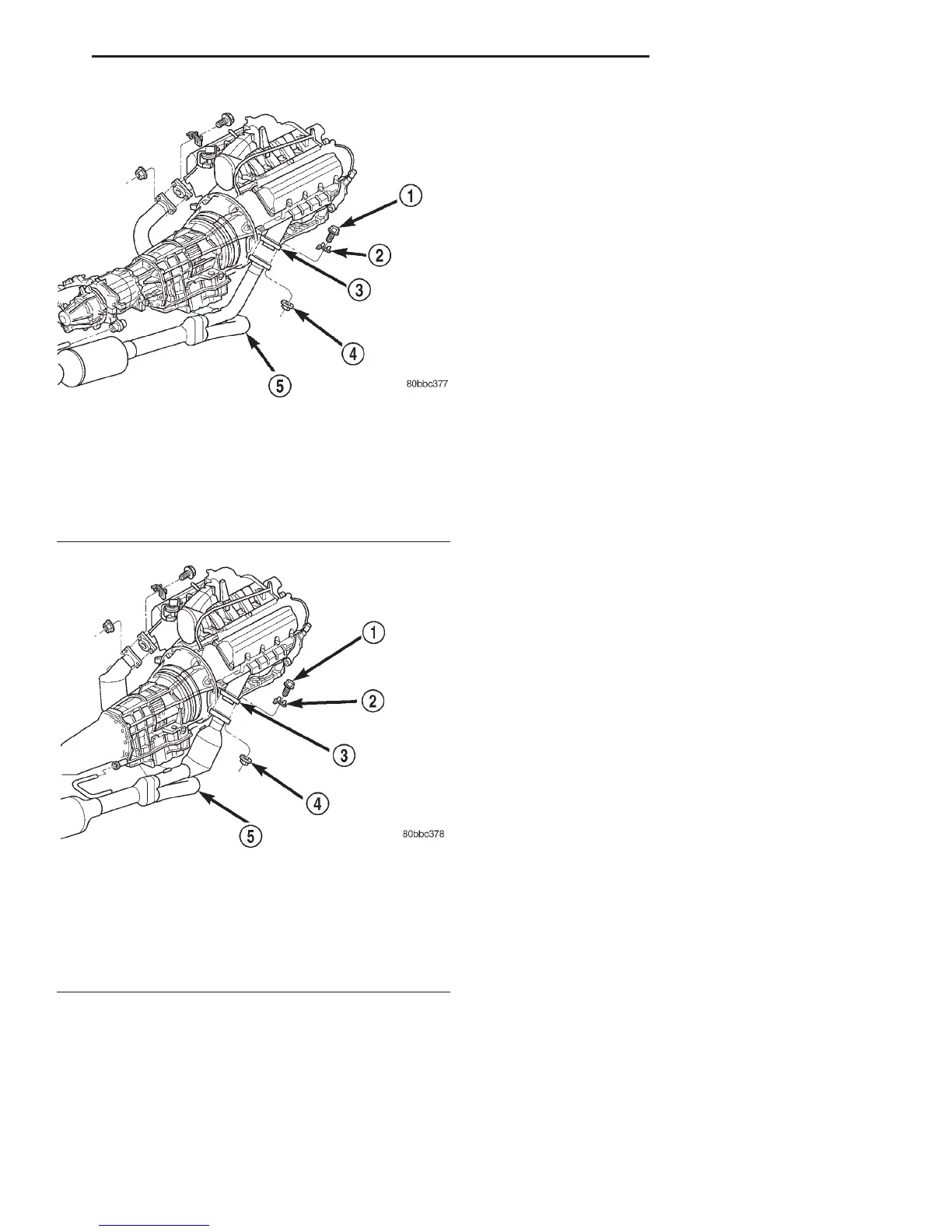
Fig. 8 Exhaust Pipe(s) to Manifold Connection—
(4.7L Federal Models)
1 – BOLT
2 – RETAINER
3 – EXHAUST MANIFOLD
4 – NUT
5 – EXHAUST PIPE
Fig. 9 Exhaust Pipe(s) to Manifold Connection—
(4.7L California Models)
1 – BOLT
2 – RETAINER
3 – EXHAUST MANIFOLD
4 – NUT
5 – EXHAUST PIPE
DN EXHAUST SYSTEM 11 - 5
REMOVAL AND INSTALLATION (Continued)