The engine wiring harness connector for each fuel
injector is equipped with an attached numerical tag
(INJ 1, INJ 2 etc.). This is used to identify each fuel
injector.
The injectors are energized individually in a
sequential order by the powertrain control module
(PCM). The PCM will adjust injector pulse width by
switching the ground path to each individual injector
on and off. Injector pulse width is the period of time
that the injector is energized. The PCM will adjust
injector pulse width based on various inputs it
receives.
Battery voltage is supplied to the injectors through
the ASD relay.
The PCM determines injector pulse width based on
various inputs.
FUEL RAIL—3.9/5.2/5.9L ENGINES
DESCRIPTION
The fuel injector rail is used to attach the fuel
injectors to the engine. It is mounted to the engine
(Fig. 5).
OPERATION
High pressure from the fuel pump is routed to the
fuel rail. The fuel rail then supplies the necessary
fuel to each individual fuel injector.
A fuel pressure test port is located on the fuel rail.
A quick-connect fitting with a safety latch clip is
used to attach the fuel line to the fuel rail.
The fuel rail is not repairable.
CAUTION: The left and right sections of the fuel rail
are connected with a flexible connecting hose. Do
not attempt to separate the rail halves at this con-
necting hose. Due to the design of this connecting
hose, it does not use any clamps. Never attempt to
install a clamping device of any kind to the hose.
When removing the fuel rail assembly for any rea-
son, be careful not to bend or kink the connecting
hose.
FUEL INJECTOR RAIL—4.7L ENGINE
DESCRIPTION
The fuel injector rail is used to mount the fuel
injectors to the engine. It is mounted to the intake
manifold (Fig. 6).
OPERATION
High pressure fuel from the fuel pump is routed to
the fuel rail. The fuel rail then supplies the neces-
sary fuel to each individual fuel injector.
A fuel pressure test port is located on the fuel rail
(Fig. 6). A quick-connect fitting with a safety latch is
used to attach the fuel line to the fuel rail.
The fuel rail is not repairable.
CAUTION: 4.7L Engine Only: The left and right sec-
tions of the fuel rail are joined with a connector
tube (Fig. 6). Do not attempt to separate the rail
halves at this tube. Due to the design of this con-
necting tube, it does not use any clamps. Never
attempt to install a clamping device of any kind to
the tube. When removing the fuel rail assembly for
any reason, be careful not to bend or kink the con-
nector tube.
FUEL TANK FILLER TUBE CAP
DESCRIPTION
The plastic fuel tank filler tube cap is threaded
onto the end of the fuel fill tube. Certain models are
equipped with a 1/4 turn cap.
OPERATION
The loss of any fuel or vapor out of fuel filler tube
is prevented by the use of a pressure-vacuum fuel fill
cap. Relief valves inside the cap will release fuel tank
pressure at predetermined pressures. Fuel tank vac-
uum will also be released at predetermined values.
This cap must be replaced by a similar unit if
replacement is necessary. This is in order for the sys-
tem to remain effective.
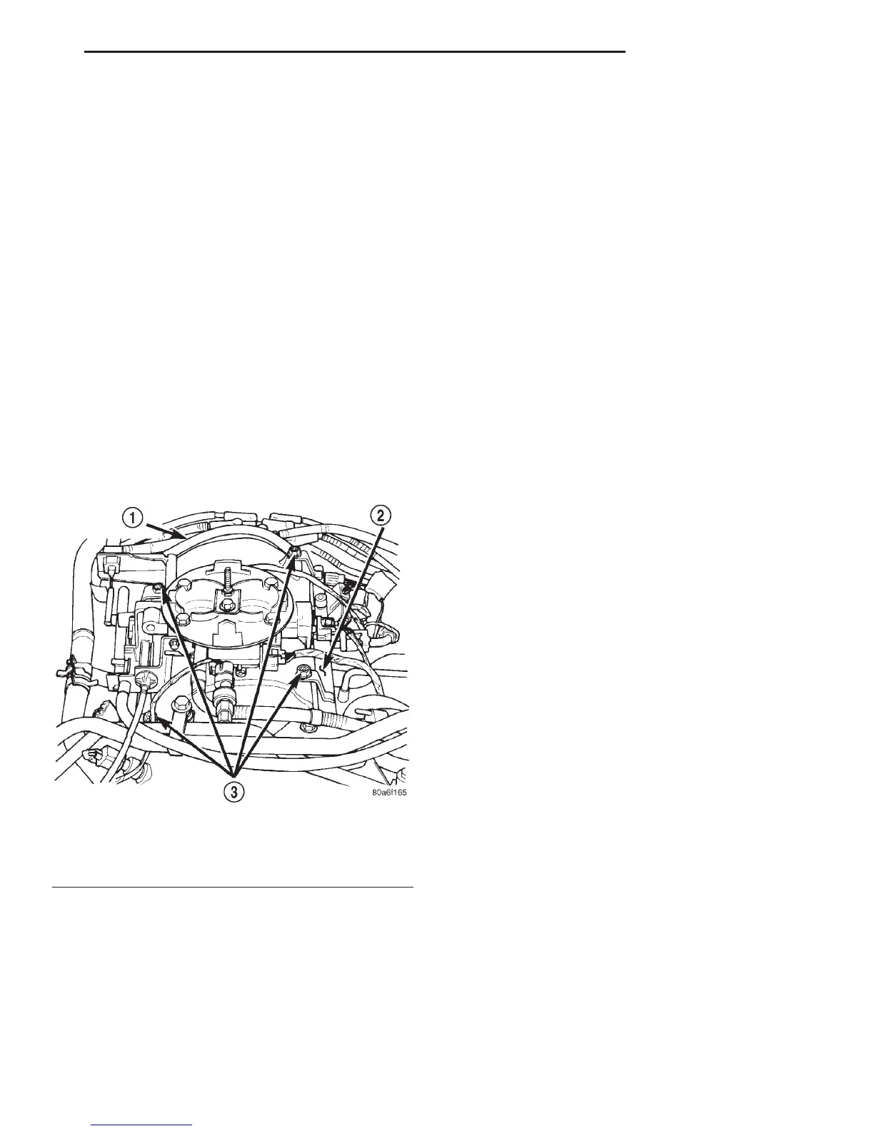
Fig. 5 Fuel Rail—3.9/5.2/5.9L Engine—Typical
1 – FUEL RAIL CONNECTING HOSE
2 – FUEL RAIL
3 – MOUNTING BOLTS (4)
DN FUEL SYSTEM 14 - 5
DESCRIPTION AND OPERATION (Continued)