CAUTION: Remove fill cap before servicing any fuel
system component to relieve tank pressure. If
equipped with a California emissions package and a
Leak Detection Pump (LDP), the cap must be tight-
ened securely. If cap is left loose, a Diagnostic
Trouble Code (DTC) may be set.
FUEL TUBES/LINES/HOSES AND CLAMPS
DESCRIPTION
Also refer to Quick-Connect Fittings.
WARNING: THE FUEL SYSTEM IS UNDER A CON-
STANT PRESSURE (EVEN WITH THE ENGINE OFF).
BEFORE SERVICING ANY FUEL SYSTEM HOSES,
FITTINGS OR LINES, THE FUEL SYSTEM PRES-
SURE MUST BE RELEASED. REFER TO THE FUEL
SYSTEM PRESSURE RELEASE PROCEDURE IN
THIS GROUP.
The lines/tubes/hoses used on fuel injected vehicles
are of a special construction. This is due to the
higher fuel pressures and the possibility of contami-
nated fuel in this system. If it is necessary to replace
these lines/tubes/hoses, only those marked EFM/EFI
may be used.
If equipped: The hose clamps used to secure rub-
ber hoses on fuel injected vehicles are of a special
rolled edge construction. This construction is used to
prevent the edge of the clamp from cutting into the
hose. Only these rolled edge type clamps may be
used in this system. All other types of clamps may
cut into the hoses and cause high-pressure fuel leaks.
Use new original equipment type hose clamps.
QUICK-CONNECT FITTINGS
DESCRIPTION
Different types of quick-connect fittings are used to
attach various fuel system components, lines and
tubes. These are: a single-tab type, a two-tab type or
a plastic retainer ring type. Some are equipped with
safety latch clips. Some may require the use of a spe-
cial tool for disconnection and removal. Refer to
Quick-Connect Fittings Removal/Installation for more
information.
CAUTION: The interior components (o-rings, clips)
of quick-connect fittings are not serviced sepa-
rately, but new plastic spacers are available for
some types. If service parts are not available, do
not attempt to repair the damaged fitting or fuel line
(tube). If repair is necessary, replace the complete
fuel line (tube) assembly.
DIAGNOSIS AND TESTING
FUEL PUMP PRESSURE TEST
Use this test in conjunction with the Fuel Pump
Capacity Test, Fuel Pressure Leak Down Test and
Fuel Pump Amperage Test found elsewhere in this
group.
Check Valve Operation: The electric fuel pump
outlet contains a one-way check valve to prevent fuel
flow back into the tank and to maintain fuel supply
line pressure (engine warm) when pump is not oper-
ational. It is also used to keep the fuel supply line
full of gasoline when pump is not operational. After
the vehicle has cooled down, fuel pressure may drop
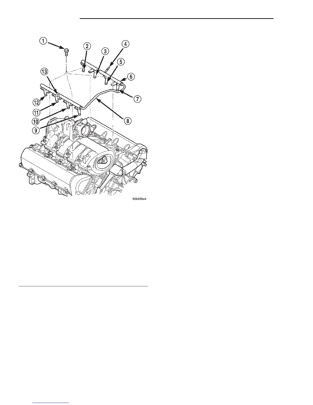
Fig. 6 Fuel Injector Rail—4.7L V-8 Engine
1 – MOUNTING BOLTS (4)
2 – INJ.#7
3 – INJ.#5
4 – QUICK-CONNECT FITTING
5 – INJ.#3
6 – FUEL INJECTOR RAIL
7 – INJ.#1
8 – CONNECTOR TUBE
9 – INJ.#2
10 – INJ.#4
11 – INJ.#6
12 – INJ.#8
13 – PRESSURE TEST PORT CAP
14 - 6 FUEL SYSTEM DN
DESCRIPTION AND OPERATION (Continued)