(3)
Install the C-clip in the groove. Slide the tripod
out against the clip. Install the snap ring in the inner
groove. Be sure the snap ring and C-clip are seated.
(4) Apply the required quantity of lubricant to the
housing and boot. Coat the interior of the joint hous-
ing and the tripod.
(5) Insert and seat the tripod and shaft in the
housing.
(6) Position the large-diameter end of the inner
C/V joint boot over the edge of the housing. Insert
the lip of the boot into the locating groove at the edge
of the housing (Fig. 11).
(7) Insert the small lip into the locating groove in
the interconnecting shaft.
(8) Retain the small–diameter of the boot on the
shaft with a ladder-type clamp in the boot groove.
Verify that the boot and lip are properly positioned
on the intermediate shaft. Position the clamp locat-
ing tabs in the slots and tighten the clamp.
(9)
Compress the clamp bridge with Remover/In-
staller C-4124. Squeeze the tool handles to complete
the tightening of the clamp (Fig. 12). Care must be
exercised when using the tool to avoid cutting
through the clamp bridge or damaging the boot.
(10) Position the large-diameter end of the boot on
the C/V joint housing.
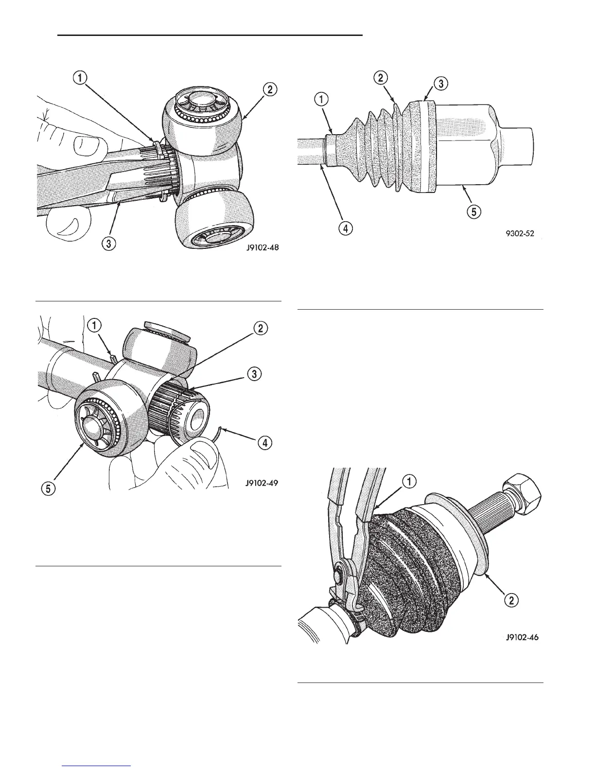
Fig. 9 Snap Retaining Ring Removal
1 – SNAP RING
2 – TRIPOD JOINT
3 – SNAP RING PLIERS
Fig. 10 C-Clip Removal/Installation
1 – SNAP RING
2 – CHAMFERED EDGE
3 – C-CLIP GROOVE
4 – C-CLIP
5 – TRIPOD
Fig. 11 Inner C/V Joint Boot
1 – SMALL CLAMP
2 – SEALING BOOT
3 – LARGE CLAMP
4 – INTERCONNECTING SHAFT
5 – INNER TRIPOD JOINT
Fig. 12 Compressing Clamp Bridge
1 – TOOL C-4124
2 – SLINGER
DN FRONT AXLE DRIVESHAFTS 3 - 23
DISASSEMBLY AND ASSEMBLY (Continued)