(11) After the inner joint boot small clamp is
installed, the inboard hub must be set to a service
build length.
(a) Compress the inner hub down the connector
shaft.
(b) Use a small blunt drift between the large
end and the boot seal to relieve the pressure.
(c) The distance edge of the lip to the edge of the
flange should be 181.00 mm (7.13 in.). This will
eliminate excess air that can cause a ballooning
affect and possibly cause damage to the boot.
(12) Verify that the boot is not twisted and that it
is correctly positioned on the housing.
(13) Install the large ladder clamp on the boot and
secure as done with the small ladder clamp (Fig. 12).
OUTER C/V JOINT
If the outer C/V joint is excessively worn, replace
the entire C/V joint and boot.
DISASSEMBLY
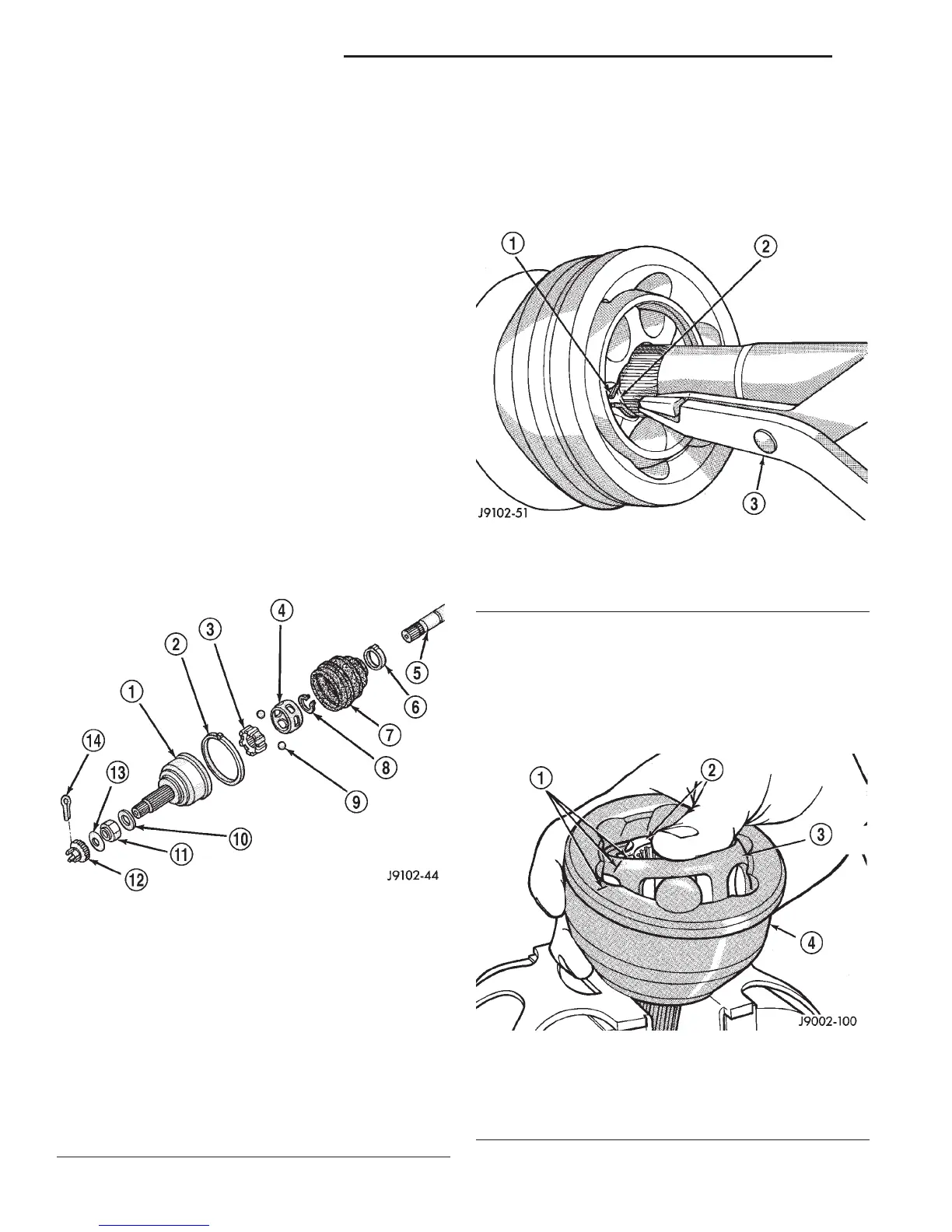
(1) Remove retaining clamps from the outer C/V
joint and discard. Slide the boot off the outer joint
and down the shaft.
(2) Remove the lubricant to expose the outer C/V
joint components (Fig. 13).
(3) Clamp the shaft in a vise (with soft jaws). Sup-
port the outer C/V joint.
(4) Use snap ring pliers to release the clip from
the groove.
(5) Slide the outer C/V joint from the shaft (Fig.
14).
(6) Remove the slinger, if damaged, from the outer
C/V joint. Use a brass drift and a hammer. Tap
slinger ring off C/V joint and discard.
(7) Remove the old lubricant. Apply installation
alignment marks on the bearing hub, bearing cage
and housing with dabs of paint (Fig. 15).
Fig. 13 Outer C/V Joint Components
1 – RZEPPA JOINT HOUSING (OUTER)
2 – CLAMP
3 – BEARING HUB
4 – BEARING CAGE
5 – SHAFT
6 – CLAMP
7 – BOOT
8 – SNAP RING
9 – BALLS (6)
10 – WASHER
11 – HUB NUT
12 – NUT LOCK
13 – SPRING WASHER
14 – COTTER PIN
Fig. 14 Outer C/V Joint Removal
1 – SNAP RING
2 – SNAP RING GROOVE
3 – SNAP RING PLIERS
Fig. 15 Ball Access
1 – INSTALLATION ALIGNMENT MARKS
2 – BEARING HUB
3 – BEARING CAGE
4 – CV JOINT HOUSING (OUTER)
3 - 24 FRONT AXLE DRIVESHAFTS DN
DISASSEMBLY AND ASSEMBLY (Continued)