(1) Using a new gasket, position fuel pump module
into opening in fuel tank. Be sure rubber gasket
remains in place. Rotate pump module assembly
until module is positioned as shown in (Fig. 25). This
step must be followed to prevent float/float rod from
contacting sides of fuel tank.
(2) Before installing lockring, apply a small
amount of engine oil to 6 fingers where fingers meet
lockring (to act as a lubricant).
(3) Position lockring over top of fuel pump module.
Tighten finger tight.
(4) Install (rotate) lockring clockwise using a brass
or bronze drift punch and a hammer. Continue rotat-
ing lockring until 6 fingers (Fig. 25) drop into 6 fin-
ger locks and lock tab (Fig. 25) falls into lockring
notch.
(5) Install fuel tank. Refer to Fuel Tank Installa-
tion in this section.
FUEL PUMP INLET FILTER
The fuel pump inlet filter (strainer) is located on
the bottom of the fuel pump module (Fig. 26). The
fuel pump module is located inside of fuel tank.
REMOVAL
(1) Remove fuel tank. Refer to Fuel Tank Removal/
Installation.
(2) Remove fuel pump module. Refer to Fuel Pump
Module Removal/Installation.
(3) Remove filter by carefully prying 2 lock tabs at
bottom of module with 2 screwdrivers. Filter is
snapped to module.
(4) Clean bottom of pump module.
INSTALLATION
(1) Snap new filter to bottom of module. Be sure
o-ring is in correct position.
(2) Install fuel pump module. Refer to Fuel Pump
Module Removal/Installation.
(3) Install fuel tank. Refer to Fuel Tank Removal/
Installation.
FUEL GAUGE SENDING UNIT
The fuel gauge sending unit (fuel level sensor) and
float assembly is located on the side of fuel pump
module (Fig. 27). The fuel pump module is located
inside of fuel tank.
REMOVAL
(1) Remove fuel tank. Refer to Fuel Tank Removal/
Installation.
(2) Remove fuel pump module. Refer to Fuel Pump
Module Removal/Installation.
(3) Unplug 4–way electrical connector (Fig. 27).
(4) Disconnect 2 sending unit wires at 4–way con-
nector. The locking collar of connector must be
removed before wires can be released from connector.
Note location of wires within 4–way connector.
(5) The sending unit is retained to pump module
with a small lock tab and notch (Fig. 28). Carefully
push lock tab to the side and away from notch while
sliding sending unit downward on tracks for removal.
Note wire routing while removing unit from module.
Fig. 26 Fuel Pump Inlet Filter
1 – FUEL PUMP INLET FILTER
2 – LOCK TABS (2)
3 – FUEL PUMP MODULE (BOTTOM)
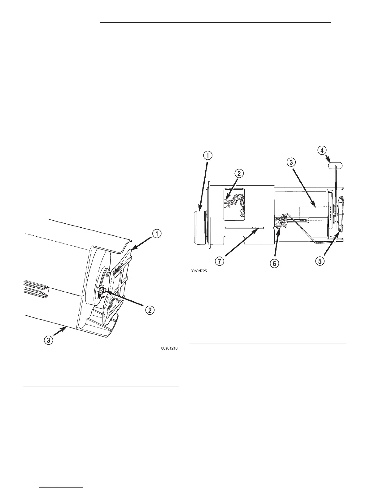
Fig. 27 Fuel Gauge Sending Unit Location—
TYPICAL Module
1 – FUEL FILTER/PRESSURE REGULATOR
2 – ELECTRICAL CONNECTOR
3 – ELECTRIC FUEL PUMP
4 – FUEL GAUGE FLOAT
5 – FUEL PUMP INLET FILTER
6 – FUEL GAUGE SENDING UNIT
7 – MODULE LOCK TABS (3)
14 - 16 FUEL SYSTEM DN
REMOVAL AND INSTALLATION (Continued)