INSTALLATION
(1) Position sending unit into tracks. Note wire
routing.
(2) Push unit on tracks until lock tab snaps into
notch.
(3) Connect 2 sending unit wires into 4–way con-
nector and install locking collar.
(4) Connect 4–way electrical connector to module.
(5) Install fuel pump module. Refer to Fuel Pump
Module Removal/Installation.
(6) Install fuel tank. Refer to Fuel Tank Removal/
Installation.
FUEL INJECTOR RAIL—3.9/5.2/5.9L ENGINES
WARNING: THE FUEL SYSTEM IS UNDER A CON-
STANT PRESSURE (EVEN WITH ENGINE TURNED
OFF). BEFORE SERVICING FUEL RAIL ASSEMBLY,
FUEL SYSTEM PRESSURE MUST BE RELEASED.
To release fuel pressure, refer to Fuel System Pres-
sure Release Procedure in this group.
CAUTION: The left and right fuel rails are replaced
as an assembly. Do not attempt to separate rail
halves at connecting hose (Fig. 29). Due to the
design of this connecting hose, it does not use any
clamps. Never attempt to install a clamping device
of any kind to hose. When removing fuel rail
assembly for any reason, be careful not to bend or
kink connecting hose.
REMOVAL
(1) Remove negative battery cable at battery.
(2) Remove air cleaner.
(3) Perform fuel pressure release procedure.
(4) Remove throttle body from intake manifold.
Refer to Throttle Body removal in this group.
(5) If equipped with air conditioning, remove
A-shaped A/C compressor-to-intake manifold support
bracket (three bolts) (Fig. 30).
(6) Disconnect electrical connectors at all 8 fuel
injectors. To remove connector refer to (Fig. 31). Push
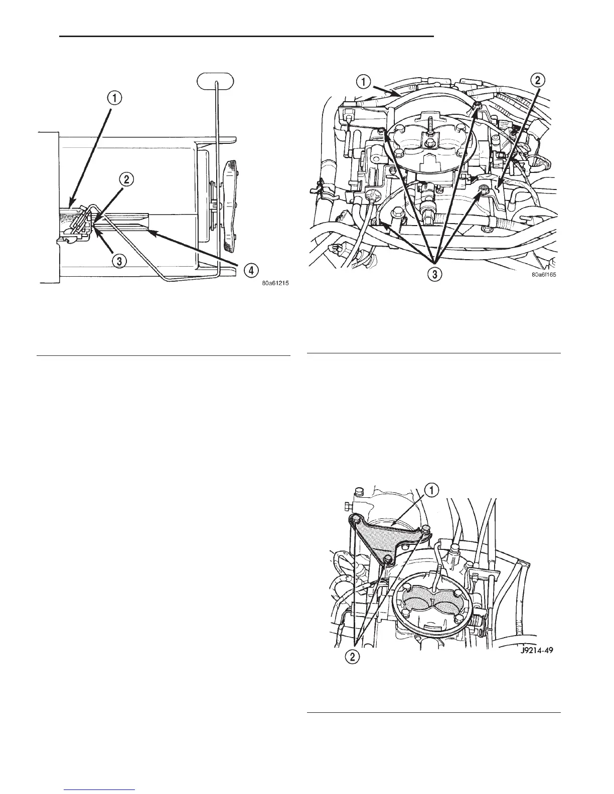
Fig. 28 Fuel Gauge Sending Unit Lock Tab/Tracks
1 – FUEL GAUGE SENDING UNIT
2 – LOCK TAB
3 – NOTCH
4 – TRACKS
Fig. 29 Fuel Rail Assembly—3.9/5.2/5.9L Engine—
Typical
1 – FUEL RAIL CONNECTING HOSE
2 – FUEL RAIL
3 – MOUNTING BOLTS (4)
Fig. 30 A/C Compressor Support Bracket—Typical
1 – AIR CONDITIONING COMPRESSOR SUPPORT BRACKET
2 – MOUNTING BOLTS
DN FUEL SYSTEM 14 - 17
REMOVAL AND INSTALLATION (Continued)