DESCRIPTION AND OPERATION
POWERTRAIN CONTROL MODULE (PCM)
DESCRIPTION
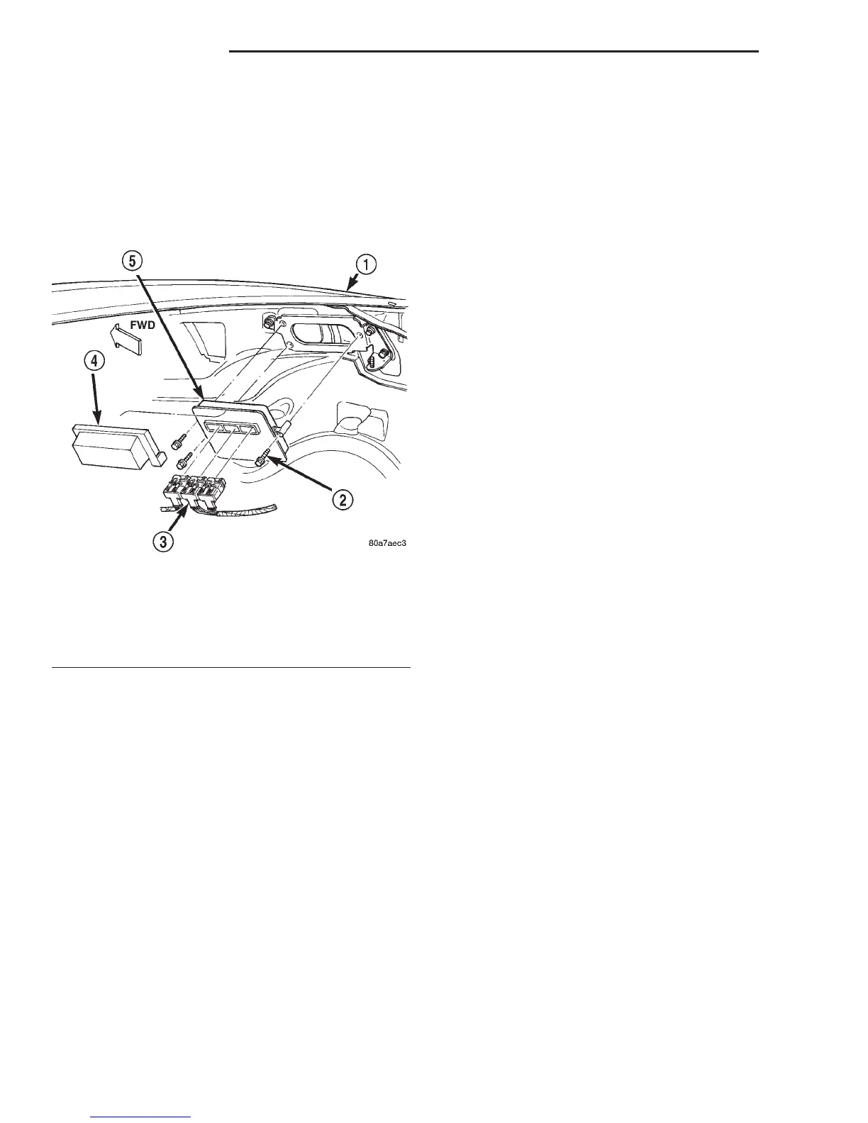
The Powertrain Control Module (PCM) (Fig. 1) is
located in the engine compartment. The PCM is
referred to as JTEC.
OPERATION
The PCM operates the fuel system. The PCM is a
pre-programmed, triple microprocessor digital com-
puter. It regulates ignition timing, air-fuel ratio,
emission control devices, charging system, certain
transmission features, speed control, air conditioning
compressor clutch engagement and idle speed. The
PCM can adapt its programming to meet changing
operating conditions.
The PCM receives input signals from various
switches and sensors. Based on these inputs, the
PCM regulates various engine and vehicle operations
through different system components. These compo-
nents are referred to as Powertrain Control Module
(PCM) Outputs. The sensors and switches that pro-
vide inputs to the PCM are considered Powertrain
Control Module (PCM) Inputs.
The PCM adjusts ignition timing based upon
inputs it receives from sensors that react to: engine
rpm, manifold absolute pressure, engine coolant tem-
perature, throttle position, transmission gear selec-
tion (automatic transmission), vehicle speed and the
brake switch.
The PCM adjusts idle speed based on inputs it
receives from sensors that react to: throttle position,
vehicle speed, transmission gear selection, engine
coolant temperature and from inputs it receives from
the air conditioning clutch switch and brake switch.
Based on inputs that it receives, the PCM adjusts
ignition coil dwell. The PCM also adjusts the gener-
ator charge rate through control of the generator
field and provides speed control operation.
NOTE: PCM Inputs:
• A/C request (if equipped with factory A/C)
• A/C select (if equipped with factory A/C)
• Auto shutdown (ASD) sense
• Battery temperature
• Battery voltage
• Brake switch
• CCD bus (+) circuits
• CCD bus (-) circuits
• Camshaft position sensor signal
• Crankshaft position sensor
• Data link connection for DRB scan tool
• Engine coolant temperature sensor
• Fuel level
• Generator (battery voltage) output
• Ignition circuit sense (ignition switch in on/off/
crank/run position)
• Intake manifold air temperature sensor
• Leak detection pump (switch) sense (if equipped)
• Manifold absolute pressure (MAP) sensor
• Oil pressure
• Output shaft speed sensor
• Overdrive/override switch
• Oxygen sensors
• Park/neutral switch (auto. trans. only)
• Power ground
• Sensor return
• Signal ground
• Speed control multiplexed single wire input
• Throttle position sensor
• Transmission governor pressure sensor
• Transmission temperature sensor
• Vehicle speed inputs from ABS or RWAL system
NOTE: PCM Outputs:
• A/C clutch relay
• Auto shutdown (ASD) relay
• CCD bus (+/-) circuits for: speedometer, voltme-
ter, fuel gauge, oil pressure gauge/lamp, engine temp.
gauge and speed control warn. lamp
• Data link connection for DRB scan tool
• EGR valve control solenoid (if equipped)
• EVAP canister purge solenoid
Fig. 1 PCM Location
1 – RIGHT FRONT FENDER
2 – PCM MOUNTING BOLTS (3)
3 – 32–WAY CONNECTORS (3)
4 – COVER
5 – POWERTRAIN CONTROL MODULE (PCM)
14 - 28 FUEL SYSTEM DN