Check the clutch pulley bearing for roughness or
excessive leakage of grease. Replace the bearing, if
required.
INSTALLATION
(1) Install the clutch field coil and snap ring.
(2) Install the clutch coil lead wire harness retain-
ing clip on the compressor front housing and tighten
the retaining screw.
(3) Align the rotor assembly squarely on the front
compressor housing hub.
(4) Thread the handle (Special Tool 6464 in Kit
6460) into the driver (Special Tool 6143 in Kit 6460)
(Fig. 32).
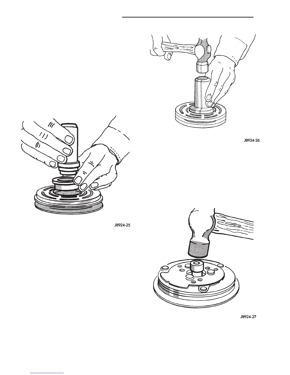
(5) Place the driver tool assembly into the bearing
cavity on the rotor. Make certain the outer edge of
the tool rests firmly on the rotor bearing inner race
(Fig. 33).
(6) Tap the end of the driver while guiding the
rotor to prevent binding. Tap until the rotor bottoms
against the compressor front housing hub. Listen for
a distinct change of sound during the tapping pro-
cess, to indicate the bottoming of the rotor.
(7) Install the external front rotor snap ring with
snap ring pliers. The bevel side of the snap ring must
be facing outward. Press the snap ring to make sure
it is properly seated in the groove.
CAUTION: If the snap ring is not fully seated in the
groove it will vibrate out, resulting in a clutch fail-
ure and severe damage to the front housing of the
compressor.
(8) Install the original clutch shims on the com-
pressor shaft.
(9) Install the clutch plate. Use the shaft protector
(Special Tool 6141-2 in Kit 6460) to install the clutch
plate on the compressor shaft (Fig. 34). Tap the
clutch plate over the compressor shaft until it has
bottomed against the clutch shims. Listen for a dis-
tinct change of sound during the tapping process, to
indicate the bottoming of the clutch plate.
(10) Replace the compressor shaft hex nut. Tighten
the nut to 14.4 N·m (10.5 ft. lbs.).
(11) Check the clutch air gap with a feeler gauge
(Fig. 35). If the air gap does not meet the specifica-
Fig. 32 Rotor Installer Set
Fig. 33 Rotor Install
Fig. 34 Clutch Plate Install
24 - 40 HEATING AND AIR CONDITIONING DN
REMOVAL AND INSTALLATION (Continued)